(No.MB366)1-13
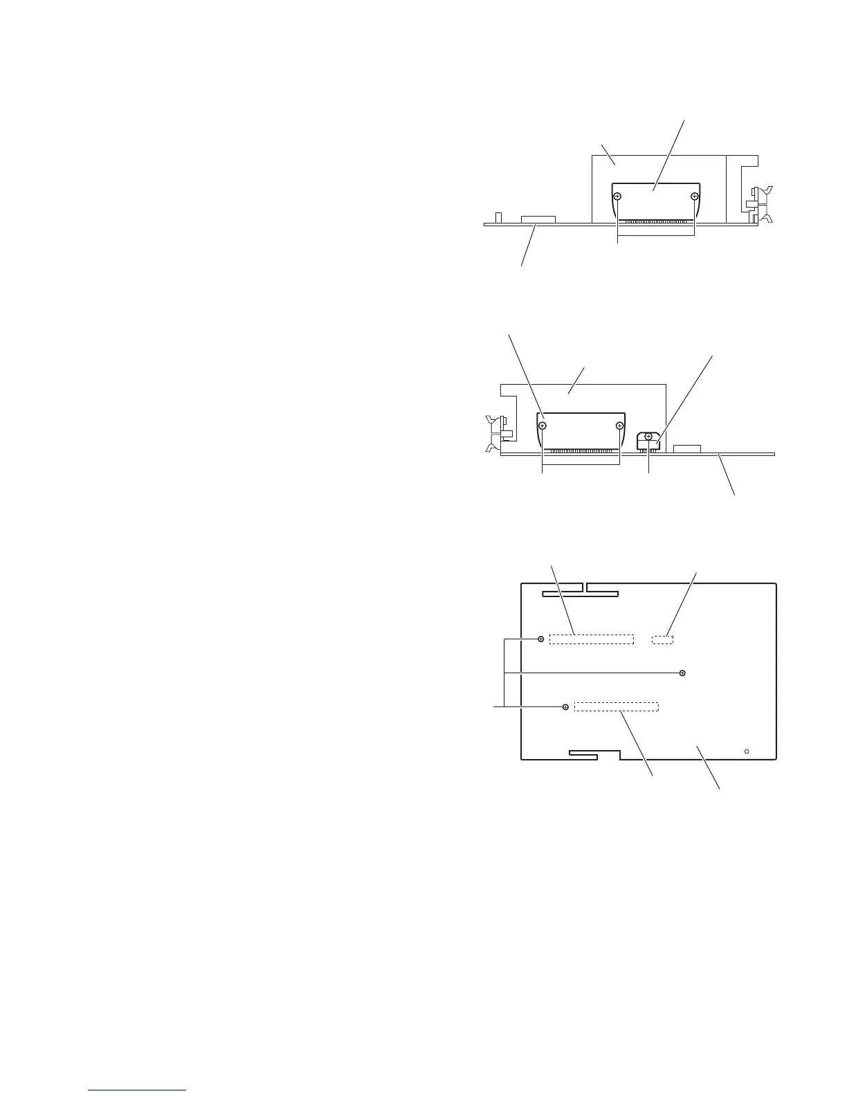
3.1.7 Removing the power amplifier ICs
(See Figs.14 to 16)
• Remove the metal cover, rear panel and amplifier board.
(1) From the forward side of the amplifier board, remove the
four screws H and screw J attaching the power amplifier
ICs to the heat sink. (See Figs.14 and 15.)
(2) From the reverse side of the amplifier board, remove the
three screws K attaching the heat sink. (See Fig.16.)
(3) Remove the soldered sections (g, h, j) and remove the
power amplifier ICs from the forward side of the amplifier
board. (See Fig.16.)
Fig.14
Fig.15
Fig.16
Amplifier board
H
Heat sink
Power amplifier IC (AIC01)
Amplifier board
H J
Heat sink
Power amplifier IC (PIC021)
Power amplifier IC (AIC02)
Amplifier board
K
g
j
h
 Loading...