1-10
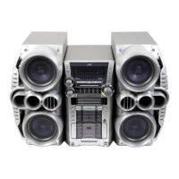
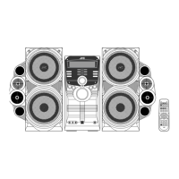
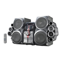
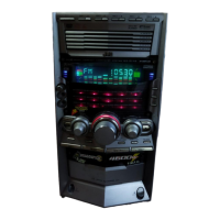
HX-Z1R
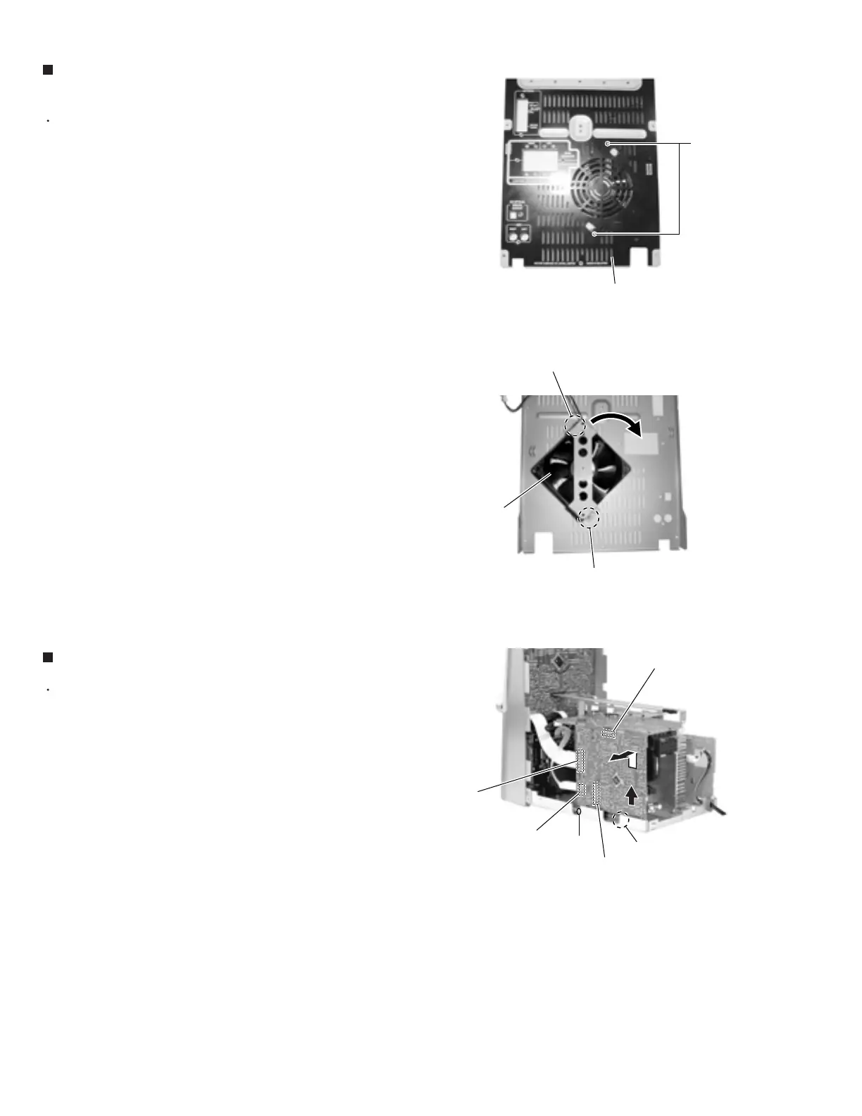
Prior to performing the following procedure, remove
the metal cover and the CD changer mechanism
assembly and the rear panel.
Remove two screws G on the rear panel.
Rotate fan assembly in clockwise direction to release
fan assembly from rear panel (joint d).
1.
2.
Removing the fan assembly
(See Fig.18, 19)
Prior to performing the following procedure, remove
the metal cover, the CD changer mechanism
assembly, the antenna board and the rear panel.
Disconnect the card wire from connector CN44 and
CN870 on the main board.
Remove the screw D attaching the board.
Disconnect connector CN217 and CN311 on the
main board outward and release from the base
chassis (joint e) upward.
1.
2.
3.
Removing the main board (See Fig.20)
Rear panel
G
Fig.18
Fig.19
Fig.20
Joint d
Joint d
Fan assembly
CN217
CN311
CN44
Joint e
D
Main board
CN870
www.freeservicemanuals.info
Digitized in Heiloo Netherlands
 Loading...