1-14
HX-Z1R
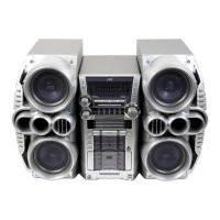
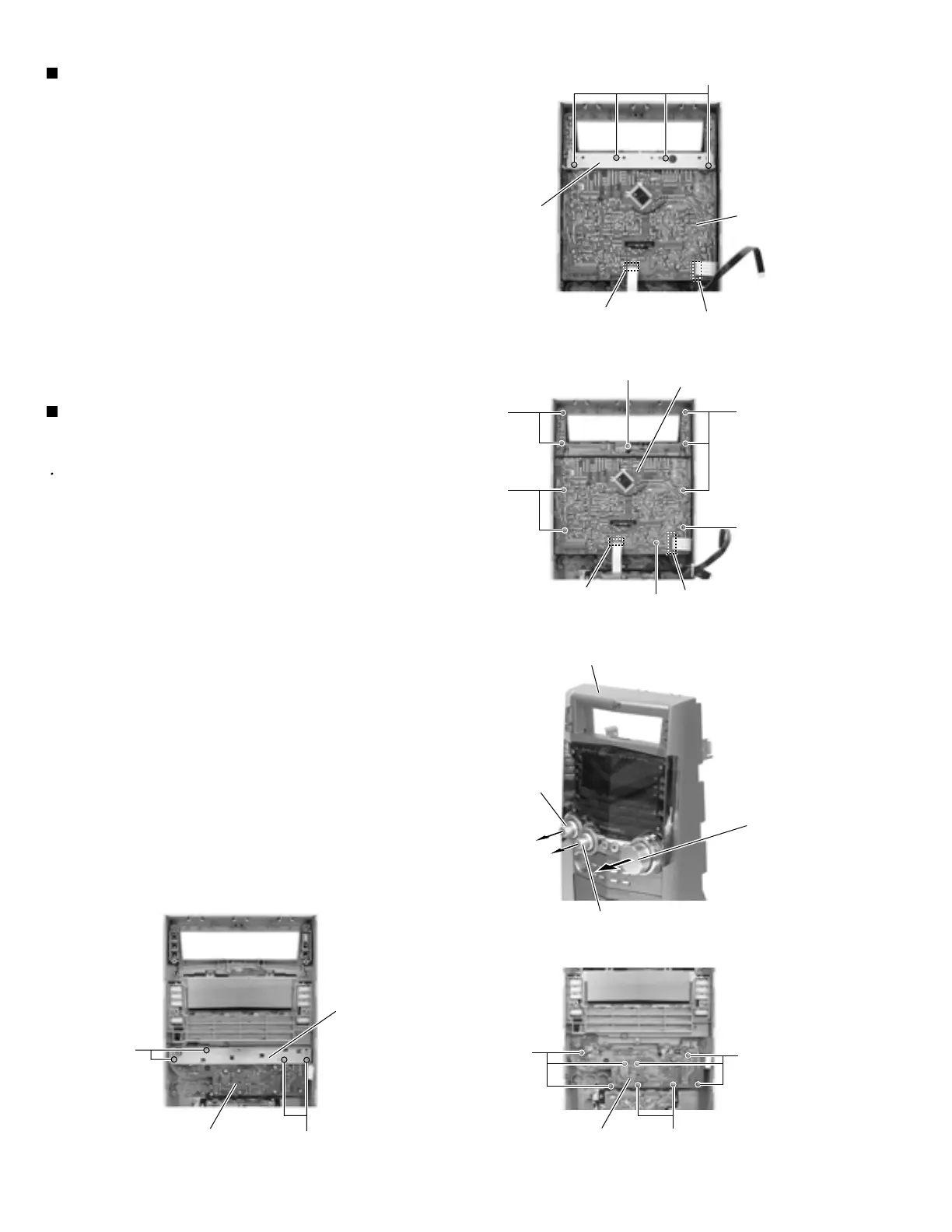
Remove the four screws S attaching the stay
bracket (1).
Disconnect the card wire from connector CN43 and
CN880 on the display system control board.
Remove the ten screws T attaching the display
system control board.
1.
2.
Removing the display system control
board (See Fig.31, 32)
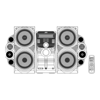
Prior to performing the following procedure, remove
the display system control board.
Pull out preset knob, sound mode knob on the front
panel toward the front.
Remove the nut at volume knob encoder from front
panel.
Remove the four screws U attaching the stay
bracket (2).
Remove the eight screws V attaching the bottom
board.
1.
2.
3.
4.
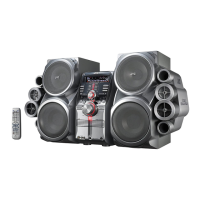
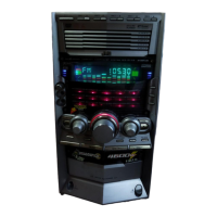
Removing the bottom board
(See Fig.33 ~ 35)
Fig.31
Fig.32
Fig.33
Fig.35Fig.34
S
T
T
T
T
T
T
U
U
V
V
V
Display system
control board
Display system control board
Stay bracket (1)
Stay bracket (2)
CN43
CN880
Front panel
Sound mode knob
Preset knob
Volume knob
CN43
CN880
Bottom board
Bottom board
www.freeservicemanuals.info
Digitized in Heiloo Netherlands
 Loading...