1-16 (No.MA046)
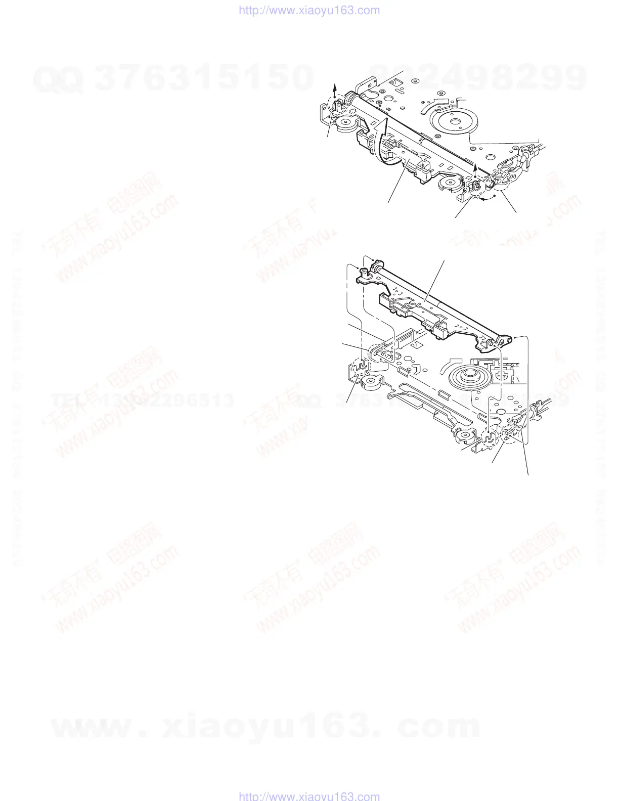
3.2.7 Removing the loading arm S.A.
(See Figs.13 and 14)
• Prior to performing the following procedures, remove the top
cover, mechanism section and front unit.
(1) From top side of the front unit, move the loading arm S.A.
from the front upwards. (See Fig.13)
(2) Release the bosses from the right and left joints m and n of
the chassis base. (See Figs.13 and 14)
(3) Release the boss from notch p of the connect arm on the
right side of the body, and release the boss from notch q of
the slide cam assembly on the left side. (See Fig.14)
Fig.13
Fig.14
Joint m
Notch p
Joint n
Loading arm S.A.
Joint m
Notch p
Joint n
Loading arm S.A.
Notch q
Side cam
assembly
Connect arm
w
w
w
.
x
i
a
o
y
u
1
6
3
.
c
o
m
Q
Q
3
7
6
3
1
5
1
5
0
9
9
2
8
9
4
2
9
8
T
E
L
1
3
9
4
2
2
9
6
5
1
3
9
9
2
8
9
4
2
9
8
0
5
1
5
1
3
6
7
3
Q
Q
TEL 13942296513 QQ 376315150 892498299
TEL 13942296513 QQ 376315150 892498299
http://www.xiaoyu163.com
http://www.xiaoyu163.com
 Loading...