2
*
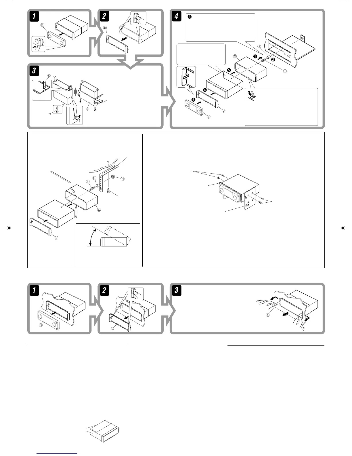
1
When you stand the receiver, be
careful not to damage the fuse on
the rear.
*
1
৹ʹጅçʮ˻ʿ࠱๑ᖢנ
௰ڄۘᎳീé
*
1
‡¡◊ËÕ§ÿ≥µ—Èß™ÿ¥ª√–°Õ∫¢÷Èπ √–«—ßլ˓∑”
„ÀÈø‘«Ï∫√‘‡«≥Ë«π∑È“¬‡’¬À“¬.
Do the required electrical connections.
නмᄔڄྐཔé
µËÕ“¬‰øµ“¡∑’Ë°”À𥉫È∑—ÈßÀ¡¥
Bend the appropriate tabs to hold the sleeve
firmly in place.
Ҿᛮጅೋڄߴдçӕࢭጅೋԕ֣Ϛ
ᄭڷػ˖é
ßÕ·ºËπ‡æ◊ËÕ¬÷¥ª≈Õ°„ÀȵËÕ°—π‡¢È“∑’Ë
When using the optional stay / ࠝΈᆊނ /
‡¡◊ËÕ„™Èµ—«¬÷¥·∫∫‡≈◊Õ°‰¥
When installing the receiver without using the sleeve / ࠝˀՠΈࢮጆೌϰ༬͵ጆ / ‡¡◊ËÕµ‘¥µ—Èß™ÿ¥ª√–
°Õ∫‚¥¬‰¡Ë„™Èª≈Õ°ÀÿÈ¡
In a car having the “Required space for installation” on page 1, first remove the car radio and install the receiver in its place.
Ϛ୶1ࡗЉīϯ༫ᄔڏĬڄԆԾçζ؛ԆԾለྐЂࡖጅ݈અЂϯ༫ϚЉᘕтé
„π√∂¬πµÏ∑’Ë¡’ “æ◊Èπ∑’Ë«Ë“ß∑’˵ÈÕß„™È„π°“√µ‘¥µ—Èß” µ“¡ÀπÈ“ 1 ¢Õ„ÀÈ∂Õ¥«‘∑¬ÿµ‘¥√∂¬πµÏÕÕ°°ËÕπ ·≈È«®÷ßµ‘¥µ—È߇§√◊ËÕßπ’È·∑π∑’Ë
Screw (option)
ᒘീ·ڄ
°√Ÿ (‡≈◊Õ°‰¥È)
Stay (option)
ᆉށ·ڄ
µ—«¬÷¥ (‡≈◊Õ°‰¥È)
Fire wall
Վػ
ºπ—ß°—π‰ø
Dashboard
ᄭڷػ
·ºßÀπÈ“ª—∑¡á
Bracket *
2
Ёࣙ *
2
·∑Ëπ√Õß√—∫ *
2
*
2
Not included for this receiver.
*
2
ʿ҉Ϛʹጅ˖é
*
2
‰¡Ë‰¥È„ÀÈ¡“°—∫™ÿ¥ª√–°Õ∫π
Flat type screws—M5 x 8 mm*
2
Ꮓᒘീ—M5 x 8 mm*
2
°√ŸÀ—«‡√’¬∫—M5 x 8 ¡‘≈≈‘‡¡µ√*
2
Flat type screws—M5 x 8 mm*
2
Ꮓᒘീ—M5 x 8 mm*
2
°√ŸÀ—«‡√’¬∫—M5 x 8 ¡‘≈≈‘‡¡µ√*
2
Bracket *
2
Ёࣙ*
2
·∑Ëπ√Õß√—∫ *
2
Note : When installing the receiver on the mounting bracket, make sure to use the 8 mm-long screws. If longer screws
are used, they could damage the receiver.
ٍิ : ӕʹጅϯ༫ϚЁࣙʕç՟·8 mmۂڄᒘീéϨس·ཫۂڄᒘീç๑ᖢʹጅé
À¡“¬‡Àµ : ‡¡◊ËÕµ‘¥µ—Èß™ÿ¥ª√–°Õ∫≈ß„π·∑Ëπ√Õß√—∫‰«È „ÀÈ„™È°√Ÿ¬“«¢π“¥ 8 ¡‘≈≈‘‡¡µ√ ∂È“„™È°√Ÿ¬“«°«Ë“π’ÈÕ“®∑”„ÀÈ™ÿ¥ª√–°Õ∫‡’¬À“¬‰¥
Removing the receiver
Before removing the receiver, release the rear section.
։͵ጆ
Ϛ؛ֈʹጅۮçᏻઅʹጅ݈௰ڄ֣׆֜௰˜ᖑළé
Insert the two handles, then pull them as illustrated so
that the receiver can be removed.
ݝ࿌Εçઅղػܓӕ˾ʈᆥç݈ძᗌ
ϙનղώղӕ˾çʹጅᎲ˃é
„˧—π∫—ߧ—∫
2
Õ—π≈ß„π√ËÕß”À√—∫„™Èæ—π≈«¥ ¥—ß¿“æ ®“°π—Èπ
„Àȇ≈◊ËÕπ™ÿ¥ª√–°Õ∫ÕÕ° „π¢≥–∑’˧ËÕ¬ Ê¥÷ߧ—π∫—ߧ—∫∑—Èß Õß
Õ—πÕÕ°®“°°—π
°“√∂Õ¥™ÿ¥ª√–°Õ∫
°ËÕπ®–∂Õ¥™ÿ¥ª√–°Õ∫ „ÀȪ≈¥ÀπÈ“µ—¥Ë«π∑È“¬°ËÕπ
ELECTRICAL CONNECTIONS
To prevent short circuits, we recommend that you disconnect the battery’s
negative terminal and make all electrical connections before installing the
receiver.
• Be sure to ground this receiver to the car’s chassis
again after installation.
Notes:
•
Replace the fuse with one of the specified rating. If the fuse blows frequently,
consult your JVC car audio dealer.
• It is recommended to connect to the speakers with maximum power of more
than 50 W (both at the rear and at the front, with an impedance of 4 Ω to
8 Ω). If the maximum power is less than 50 W, change “Amplifier Gain”
setting to prevent the speakers from being damaged (see page 40 of the
INSTRUCTIONS).
• To prevent short-circuit, cover the terminals of the UNUSED leads with
insulating tape.
• The heat sink becomes very hot after use. Be careful not to touch it when
removing this receiver.
ྑཕો
ՎഠཔçܿᙯϚϯ༫ʹጅ˃ۮçᔃළྐЖڄ࠷çՓӕЉྐཔ௲
Ϧé
• ϰ༬ҭ݉આ͵ጆڅϚሉࡍ๙ોгԿԾê
ٍิ!
• ӕۘᎳീӦಗᖃ׆࠷மࡩڄۘᎳീéϨسۘᎳീગጛᖢçቁώ
JVC ԆԾࡖᛏ˜ኀ༿é
• ݈֜ۮಙᑵڄఛʨ᎔ʈᏻʨؠ50 Wçմۇӏ4 Ωü
8 ΩéϨسఛʨʮؠ 50 W
çቁቆīAmplifier GainĬ׆
ࡩçՎಙᑵ๑ᖢéኌ՟·იاڄ୶
40ࡗé
•
Վྐഠཔçቁ·ഽሇઘу͵՟·ྐለڄၷʪé
• ʹጅ՟·݈çಞᇊ݃ᇊéϕЏçϚ୰ʹጅçʮ˻ʿ࠱᙮ညಞ
ᇊé
°“√‡™◊ËÕ¡‚¥¬„™È‰øøÈ“
‡æ◊ËÕªÈÕß°—π°“√‡°‘¥‰øøÈ“≈—¥«ß®√ ¢Õ·π–π”„ÀȪ≈¥¢—È«·∫µ‡µÕ√’Ë≈∫ÕÕ°
·≈È«®÷ßµËÕ“¬‰ø°ËÕ𵑥µ—È߇§√◊ËÕß
• µ√«®Õ∫„ÀÈ·πË„®«Ë“‰¥È‡¥‘𓬥‘πµËÕ√–À«Ë“߇§√◊ËÕß°—∫µ—«∂—ß
√∂¬πµÏ„À¡Ë·≈È«À≈—ß®“°µ‘¥µ—Èß
À¡“¬‡Àµÿ:
• „™Èæ‘°—¥®”‡æ“–·∑πø‘« À“°ø‘«Ï¢“¥∫ËÕ¬ „ÀȪ√÷°…“√È“ π¢“¬‡§√◊ËÕ߇’¬ß√∂¬πµÏ JVC
• ¢Õ·π–π”„ÀȵËÕ≈”‚æß ∑’Ë¡’°”≈—ߢ—∫ßÿ¥‡°‘π°«Ë“ 50 W (∑—ÈߥȓπÀπÈ“·≈–¥È“πÀ≈—ß
¡’§Ë“§«“¡µÈ“π∑“π
4 Ω ∂÷ß 8 Ω)
∂È“°”≈—ߢ—∫µË”°«Ë“
50 W „Àȇª≈’ˬπ§Ë“ “Amplifier Gain” ‡æ◊ËÕªÈÕß°—
π‰¡Ë„ÀÈ≈”‚æß™”√ÿ¥ (¥ŸÀπÈ“
40 §”·π–π”)
• °“√ªÈÕß°—π°“√≈—¥«ß®√ ®–µÈÕßæ—π¢—È«“¬µ–°—Ë« ∑’ˉ¡Ë„™È·≈È«¥È«¬‡∑ ªæ—𓬉ø
• ·ºËπ√–∫“¬§«“¡√ÈÕπ®–√ÈÕπ¡“°À≈—ß®“°„™È √–¡—¥√–«—ßլ˓‰ª —¡º—‡¡◊ËÕ∂Õ¥™ÿ¥ª√–
°Õ∫π
Heat sink
ಞᇊ
·ºËπ√–∫“¬§«“¡√ÈÕπ
Do not block the fan.
ʿ࠱ۇᗉࡘ࣮é
լ˓°’¥¢«“ß∑“ß√–∫“¬Õ“°“»¢Õßæ—¥≈¡
Install the receiver at an angle of less than 30˚.
અʹጅϯ༫Ϛ˲ؠ
30
ڄԴܾé
µ‘¥µ—Èß™ÿ¥ª√–°Õ∫∑’Ë¡ÿ¡µË”°«Ë“
30
Õß»“