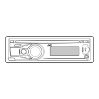
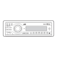
1-16 (No.MA158)
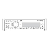
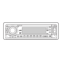
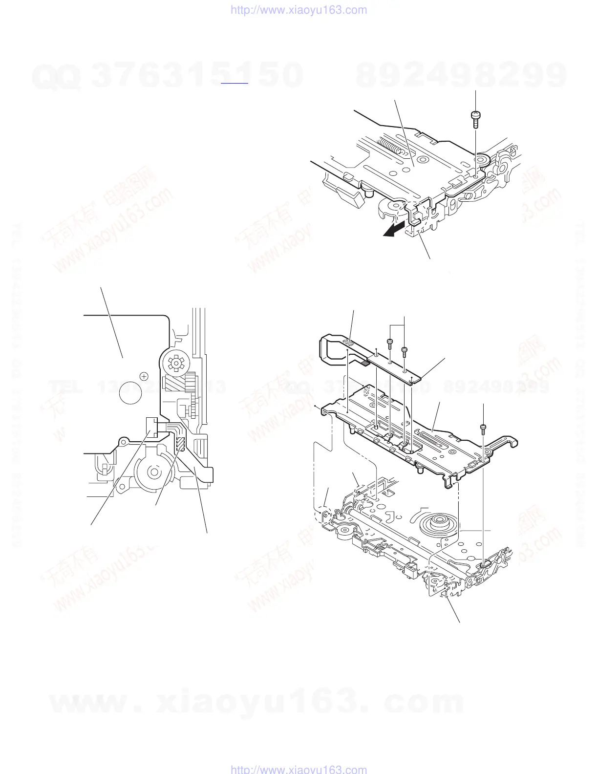
3.2.6 Removing the front unit
(See Fig.10 to 12)
• Remove the top cover and the mechanism section.
(1) Disconnect the flexible wire from connector CN202 on the
mechanism control board at the bottom of the body. (See
Fig.10.)
(2) Remove the screw G attaching the front unit on the top of
the body. (See Fig.11.)
(3) Move the front unit toward the front to release joint h, and
release two joints i and j on the right side of the chassis
base assembly. Then remove the front unit upward. (See
Figs.11 and 12.)
(4) Remove the two screws H attaching the switch board. (See
Fig.12.)
Reference:
You can remove the switch board only without removing the
front unit.
Caution:
When reassembling, attach the flexible wire extending from
the switch board using the double tape. (See Figs.10 and 12.)
Fig.10
Fig.11
Fig.12
Mechanism control board
Flexible wire
CN202
Double tape
G
Front unit
h
h
Front unit
Switch board
j
G
H
i
Double tape
w
w
w
.
x
i
a
o
y
u
1
6
3
.
c
o
m
Q
Q
3
7
6
3
1
5
1
5
0
9
9
2
8
9
4
2
9
8
T
E
L
1
3
9
4
2
2
9
6
5
1
3
9
9
2
8
9
4
2
9
8
0
5
1
5
1
3
6
7
3
Q
Q
TEL 13942296513 QQ 376315150 892498299
TEL 13942296513 QQ 376315150 892498299
http://www.xiaoyu163.com
http://www.xiaoyu163.com
 Loading...