1-20 (No.MA158)
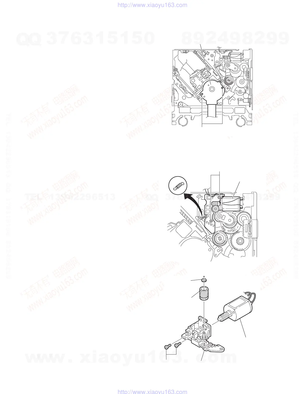
3.2.10 Removing the spindle motor
(See Fig.20)
• Remove the mechanism control board.
Remove the two screws L attaching the spindle motor on the
bottom of the body.
Caution:
Perform adjustment when reattaching the spindle motor.
Fig.20
3.2.11 Removing the feed motor assembly
(See Fig.21 and 22)
• Remove the mechanism control board.
(1) Remove the feed TRI. spring on the bottom of the body.
(See Fig.21.)
(2) Remove the two screws M attaching the feed motor as-
sembly. (See Fig.21.)
(3) Remove the slit washer from the motor H. assembly and
pull out the worm wheel. (See Fig.22.)
Remove the two screws N attaching the feed motor. (See
Fig.22.)
Fig.21
Fig.22
L
Spindle motor
M
Feed motor assembly
Feed TRI. spring
Feed moto
Motor H. assembly
Worm wheel
Slit washer
N
w
w
w
.
x
i
a
o
y
u
1
6
3
.
c
o
m
Q
Q
3
7
6
3
1
5
1
5
0
9
9
2
8
9
4
2
9
8
T
E
L
1
3
9
4
2
2
9
6
5
1
3
9
9
2
8
9
4
2
9
8
0
5
1
5
1
3
6
7
3
Q
Q
TEL 13942296513 QQ 376315150 892498299
TEL 13942296513 QQ 376315150 892498299
http://www.xiaoyu163.com
http://www.xiaoyu163.com
 Loading...