42
ENGLISH
Data Size: B6L (182 mm x 128 mm)
Book Size: B6L (182 mm x 128 mm)
Installation/Connection
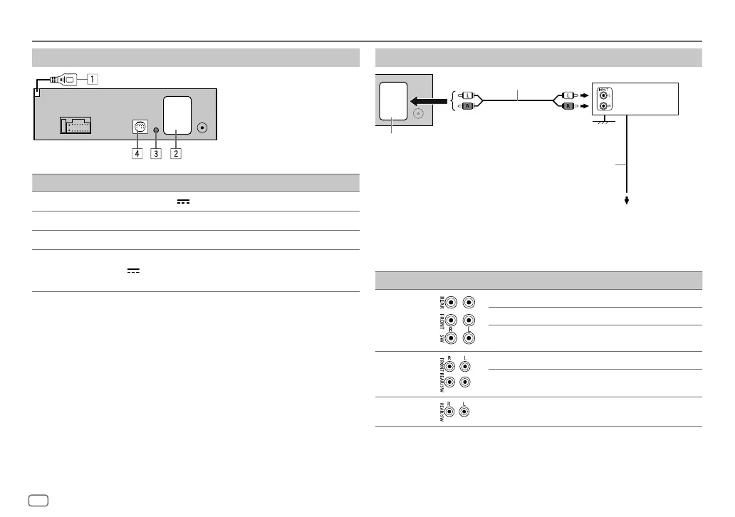
Connect external components
No Part
1
For KD-T925BTS: USB cable (DC 5 V 1.5 A) (approx. 1 m/3.3 feet)
2
Output terminals (See “Connect external amplifiers via output terminals”.)
3
Microphone input jack (page 16)
4
For KD-T925BTS/KD-T920BTS:
Expansion port (12 V
500 mA): To the optional SiriusXM Vehicle Tuner (commercially
available). (Page 12)
Connect external amplifiers via output terminals
* Firmly connect the ground wire of the amplifier to the car’s chassis to avoid damaging the unit.
Model Output terminals 2-way crossover 3-way crossover
KD-T925BTS
REAR: Rear output Tweeter output
FRONT: Front output Mid Range output
SW: Subwoofer output Woofer output
KD-T920BTS
FRONT: Front output Mid Range output
REAR/SW: Rear/subwoofer output Woofer output
KD-T720BT
REAR/SW: Rear/subwoofer output Woofer output
JVC Amplifier*
Signal cord (not supplied)
To remote lead (blue/white) of the
wiring harness. (Page 41)
Remote wire (not supplied)
Output terminals
KD_T925BTS_K_B5A-3880-00_EN_2nd Draft.indd 42KD_T925BTS_K_B5A-3880-00_EN_2nd Draft.indd 42 5/7/2021 10:55:06 AM5/7/2021 10:55:06 AM
 Loading...