Do you have a question about the JVC KS-AX6500 and is the answer not in the manual?
Unit operates on 12V DC, NEGATIVE ground electrical systems.
Specific precautions for floating ground system (speaker terminals).
Explains Normal mode and Bridge mode connections for speakers.
Lists max output power for models in Normal and Bridge modes.
Illustrates mounting spots like under seat or trunk floor.
Avoid inflammable objects, ensure heat dissipation, use provided hardware.
Details connecting speakers in normal mode for KS-AX6700.
Instructions for connecting amplifier without a line output.
Details connecting speakers in normal mode for KS-AX6500/KS-AX6300.
Details connecting speakers in bridge mode for KS-AX6700.
Details connecting speakers in bridge mode for KS-AX6500/KS-AX6300.
Instructions to prevent short circuits during power connection.
Connecting the remote turn-on lead or accessory circuit.
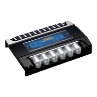
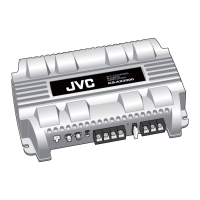
Identifies the control panel window and its illumination.
Adjusts 45 Hz frequency boost from 0 dB to +12 dB.
Adjusts input signal levels (HIGH/LOW) for optimal volume matching.
Sets crossover frequency from 50 Hz to 250 Hz.
Selects OFF, LPF (subwoofer), or HPF (high-pass) filter settings.
Checks for blown fuse, ground connection, and unit power.
Checks speaker impedance and wiring for short circuits.
Checks PROTECTOR lamp, remote lead, RCA connections, and grounding.
Managing cable placement and ground connections to reduce noise.
Details power output, impedance, frequency response for normal mode.
Details power output, impedance, frequency response for bridge mode.
Covers power requirements, grounding, dimensions, mass, and accessories.
| Number of Channels | 4 |
|---|---|
| Signal to Noise Ratio | 100dB |
| RMS Power at 2 Ohms | 90W x 4 |
| Bridged RMS Power at 4 Ohms | 180W x 2 |
| Total RMS Power Output | 360W |
| Frequency Response | 10Hz - 30kHz |
| Crossover Frequency | 50Hz - 200Hz |
| Crossover | LP/HP |
| Bass Boost | 0-18 dB |
| Amplifier Class | Class AB |
| Fuse Rating | 30A |
| Input Sensitivity | 200mV - 4V |