Do you have a question about the JVC MX-J950R and is the answer not in the manual?
| Brand | JVC |
|---|---|
| Model | MX-J950R |
| Category | Stereo System |
| Language | English |
General safety instructions for handling the product and replacement parts.
Warning against unauthorized design alterations and their consequences.
Notes on safety-related characteristics and replacement parts.
Precautions for handling leads, tubing, and barriers.
Procedure for checking leakage current after reassembly.
Warning about proper repair and safety standards.
Identifies the product as a Class 1 Laser Product.
Warning about laser radiation from open/defeated light-lock.
Caution regarding no serviceable parts inside and not disassembling.
Caution about compact player and safety switches.
Caution regarding laser radiation prevention.
Caution on controls, adjustments, and performance.
Displays warning labels related to laser products.
ESD precautions to prevent damage from static electricity.
Earth processing for laser diode, optical pick-up.
Grounding the workbench for static discharge.
Using an anti-static wrist strap for grounding.
Handling precautions for the optical pickup during installation.
Precautions for handling the traverse unit due to shock sensitivity.
Special notes when the traverse unit is decomposed.
Steps for removing metal cover and discharging capacitors.
Setting electrical resistance for discharging capacitors.
General warnings, cautions, and notes for the user.
Information regarding product registration and support contact.
Information about the manual's purpose and usage.
General precautions to be taken by the user.
List of operational topics covered in the manual.
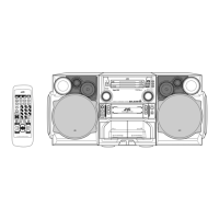
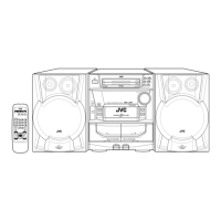
Identification of controls on the front panel.
Identification of controls on the powered front panel.
Description of the display window indicators.
Identification of controls on the remote control.
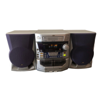
Instructions for unpacking the unit.
Steps for connecting external equipment.
Guide for connecting audio devices for English display.
Instructions for installing batteries in the remote control.
How to attach the FM antenna.
Procedures for setting the clock.
How to adjust the volume.
How to adjust the tone controls.
How to select the audio source.
Steps to turn the unit on and off.
Detailed steps for setting the clock.
How to tune into FM and AM radio stations.
Procedures for tuning into radio stations.
How to store and recall preset stations.
How to change FM reception mode.
How to receive FM stations with RDS data.
Temporarily switching to program type.
How to change PTY codes for FM stations.
Basic instructions for playing back CDs.
How to select specific tracks on a CD.
Playing the entire disc continuously.
Steps to load CDs into the player.
Instructions for placing additional CDs.
How to program the playback order of CDs.
Instructions for playing back cassette tapes.
Steps to play back a cassette tape.
How to modify programmed playback.
How to repeat tracks or entire CDs.
Searching for the beginning of a song.
How to record a tape on Deck B.
Recording to tape or direct CD recording.
Safety measures to protect speakers.
Tips for optimal recording quality.
Instructions for dubbing tapes.
How to start recording.
Recording on both sides in reverse mode.
How to perform auto edit recording.
Recording operations specific to the unit.
How to use the daily timer function.
Steps to set the timer.
How to set the timer's on-time.
How to set the timer's off-time.
How to cancel or turn off the timer.
Timer operations specific to the unit.
Precautions for handling components.
Precautions for handling assemblies.
Common troubleshooting issues and solutions.
Technical specifications for the amplifier section.
Technical specifications for the CD player section.
Technical specifications for the cassette deck section.
General specifications of the unit.
List of supplied accessories.
Explanation of PTY codes used for FM stations.
Categorization of PTY codes for FM stations.
Steps to remove the main metal cover of the unit.
Procedures for detaching the CD changer mechanism assembly.
Steps to detach the front panel assembly from the main unit.
Procedures for removing the microphone terminal board.
Steps to detach the rolling panel assembly.
Procedures for detaching the main board from the unit.
Steps to detach the cassette mechanism assembly.
Procedures for removing various boards within the front panel.
Steps to detach power, eject, and remote control boards.
Procedures for detaching relay and fixing boards.
Steps to detach the rear panel assembly.
Procedures for detaching the tuner board.
Steps to detach the input/output board.
Steps to remove the fan motor assembly.
Procedures for removing the rear cover/panel assembly.
Procedures for removing the preamplifier board and heat sink.
Procedures for removing the power and main amplifier board.
Procedures for removing the multicontrol assembly.
Steps to remove the multicontrol board.
Procedures for removing the drive motor assembly.
Procedures for removing the CD servo control board.
Steps to remove the CD tray assembly.
Procedures for removing the CD loading mechanism.
Steps to remove the CD traverse mechanism.
Procedures for removing the CD pickup unit.
Procedures for removing the cam unit.
Procedures for removing the actuator motor and belt.
Procedures for removing cams and cam gear.
Procedures for removing the C.G. base assembly.
Procedures for removing playback, recording, and eraser heads.
Procedures for removing head amp and mechanism control P.C. board.
Steps to remove the capstan motor assembly.
Procedures for removing the capstan motor.
Steps to remove the flywheel.
Procedures for removing reel pulse board and solenoid.
List of instruments needed for adjustment procedures.
Specifications for radio input signal.
Frequency ranges for AM and FM.
Standard settings for volume and switches.
Important precautions during measurement.
Conditions for various measurements.
Diagram showing adjustment positions for cassette mechanism A.
Diagram showing adjustment positions on the back of cassette mechanism.
Diagram showing adjustment points within the cassette mechanism unit.
Procedure to confirm head angle.
Procedure to confirm tape speed.
Reference values for double tape speed confirmation.
Reference values for speed difference.
Reference values for wow and flutter.
Adjustment procedure for recording bias current.
Adjustment procedure for frequency characteristics.
Reference values for electrical function confirmations.
Confirmation of recording bias and playback side.
Reference value for eraser current.
Diagnosis procedure for the system control P.C. board.
Part numbers for extension wires.
Flowchart detailing operational steps until TOC read.
Instructions for cleaning the laser lens.
Symptoms related to laser diode life.
Checking RF output level for eye pattern.
Procedure for replacing the laser pickup.
Pin layout, block diagram, and pin functions for AN8806SB.
Pin layouts and diagrams for BA15218, BU4094BC, GP1U281X ICs.
Pin layout and functions for BA6897FP-W IC.
Block diagram and pin functions for LA1838 IC.
Pin layout, block diagram, and pin functions for LC72136N.
Pin layout and block diagram for TDA7439 IC.
Pin functions for MN101CP35DEA IC.
Terminal layout and block diagram for MN35510 IC.
Pin layout and block diagram for BU4094BC IC.
Pin layout and block diagram for LA72723 IC.
Block diagram of the main, cassette, and CD sections.
Block diagram of the tuner section.
Schematic diagram of the power transformer section.
Schematic for the AC230V supply block.
Explanation of the overall schematic diagram.
Schematic diagram of the power amplifier and regulator section.
Schematic diagram of the function and amplifier section.
Schematic diagram of the FL display and system controller section.
Schematic diagram of the microphone amplifier section.
Schematic diagram of the CD servo and mechanism control section.
Schematic diagram of the head amplifier and mechanism control section.
Schematic diagram of the cassette mecha control circuit.
Schematic diagram for the tuner section, specific versions.
Schematic diagram for the tuner section, specific versions.
Printed circuit board layout for main and preamplifier boards.
Printed circuit board layout for input/output and power boards.
PCB layouts for CD tray section and can switch boards.
Printed circuit board layout for the CD servo control board.
Printed circuit board layout for the cassette mechanism board.
Printed circuit board layout for the tuner board.
List of parts for the MX-J900 and MX-J950R models.
Table of contents for the parts list section.
Exploded view of the general assembly with part identification.
Exploded views for system, pre-amp, power amp, and tuner boards.
Detailed list of parts for the general assembly.
Exploded view and parts list for the CD changer mechanism.
Parts list for the CD mechanism assembly.
Exploded view and parts list for the cassette mechanism.
Identification of points requiring grease during assembly.
Electrical parts list for the power amp and source select board.
Electrical parts list for the system control board.
Electrical parts list for the CD servo board.
Electrical parts list for the tuner board, Ver. J/C, Block 03.
Electrical parts list for the tuner board, Ver. J/C, Block 04.
Electrical parts list for the parts system control board.
Electrical parts list for the CD servo board, Block 06.
Electrical parts list for the CD select switch board.
Electrical parts list for the head amplifier mechanism control board.
Electrical parts list for the cassette switch board.
Packing materials and accessories for the MX-J900 model.
Packing materials and accessories for other model variants.
List of packing parts for the MX-J900.
List of packing parts for CA and SP models.