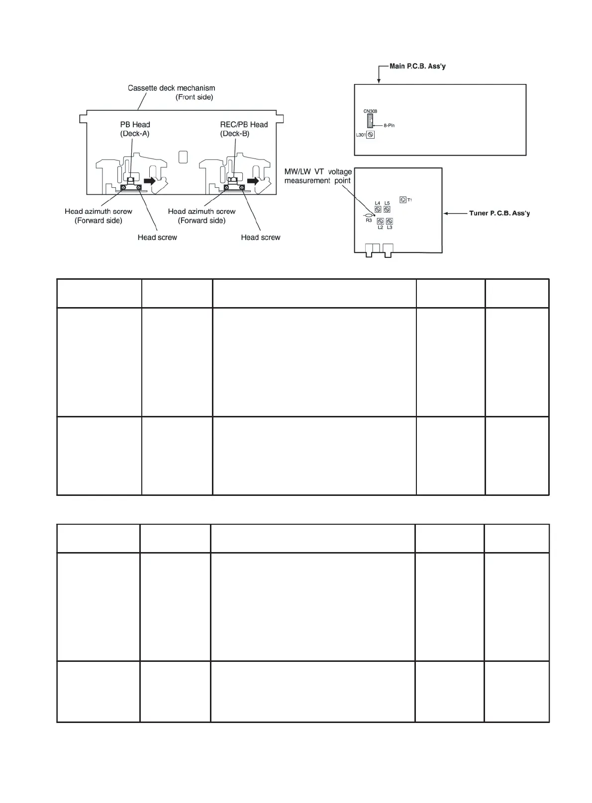
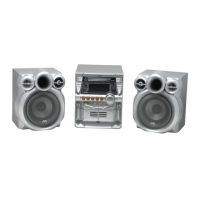
Arrangement of adjusting positions
Tape recorder section
Note: The adjustment of CD section is not required.
Tuner section
Items
Measurement
condi tions
Measurement method
Standard
values
Adjusting
posi tions
Cassette Head
Azimuth Alignments
Test tape :
VT703 (10kHz)
Measurement
output terminal :
Left and Right
speaker output
(6-ohm loaded)
or Headphone
Output
(32-ohm loaded)
1. Playback the test tape VT703 (10KHz) or equivalent.
2. Adjust the head azimuth screw to obtain maximum
output and both output of L / R is in 3dB.
3. Put on the screw lock paint after alignments.
Maximum output Head azimuth
screw
Adjust the
head azimuth
screw only
when the head
has been
changed.
Recording Bias
Frequency Alignment
Test tape :
TYPE I AC-225
Measurement
output terminal :
Erase head
terminal
(CN308 8-Pin)
1. Insert the recording tape in deck-B.
2. Starting the recording.
3. Adjust the oscillation frequency to 80KHz+/-3KHz
by core of Oscillation coil of L301.
80kHz+/-3kHz Bias coil: L301
Use the High-
Impedance
Probe or
Frequency
counter input.
Items
Measurement
condi tions
Measurement method
Standard
values
Adjusting
posi tions
AM Tracking
Alignments
Input signal :
529kHz (530kHz)
603kHz (600kHz)
Measurement
point :
Resistor(R3)
terminal
1. Set the Signal Generator signal to 529KHz (530KHz)
the feed to Loop Antenna.
2. Receiving the signal and the adjust the OSC coil
L4(MW)/L5(LW) obtain the V.T is 1.40V +/-0.05V.
3. Change the receiving frequency to 603KHz (600KHz).
4. Adjust the Antenna coil L2(MW)/L3(LW) obtain
maximum sensitivity .(Adjust the SSG output to
out of AGC range.)
V.T :
1.40V+/-0.05V
Maximum
sensitivity
OSC coil:
L4(MW)/L5(LW)
Antenna coil:
L2(MW)/L3(LW)
Adjust the OSC
coil only when
the AM coil
block has been
changed.
AM IFT Alignments Input signal :
530kHz (529kHz)
1. Set the receiving frequency to 529KHz (530KHz ).
2. Feed the 450KHz signal to AM antenna input.
3. Adjust the IFT Block T1 obtain to maximum output.
(Adjust the SSG output to out of AGC range.)
Maximum output IFT(T1)
Adjust the IFT
only when the
IFT block has
been changed.
1-20