EasyManua.ls Logo

JVC MX-KC45E User Manual

JVC MX-KC45E
71 pages
To Next Page IconTo Next Page
Page #1 background imageLoading...
Page #1 background image
SERVICE MANUAL
COPYRIGHT © 2006 Victor Company of Japan, Limited
No.MB550
2006/7
COMPACT COMPONENT SYSTEM
MB55020067
MX-KC45E,MX-KC45EN,
MX-KC45A,MX-KC45UW,
MX-KC45UY,MX-KC45UJ
Lead free solder used in the board (material : Sn-Ag-Cu, melting point : 219 Centigrade)
TABLE OF CONTENTS
1 PRECAUTION. . . . . . . . . . . . . . . . . . . . . . . . . . . . . . . . . . . . . . . . . . . . . . . . . . . . . . . . . . . . . . . . . . . . . . . . . 1-3
2 SPECIFIC SERVICE INSTRUCTIONS . . . . . . . . . . . . . . . . . . . . . . . . . . . . . . . . . . . . . . . . . . . . . . . . . . . . . . 1-5
3 DISASSEMBLY . . . . . . . . . . . . . . . . . . . . . . . . . . . . . . . . . . . . . . . . . . . . . . . . . . . . . . . . . . . . . . . . . . . . . . . 1-6
4 ADJUSTMENT . . . . . . . . . . . . . . . . . . . . . . . . . . . . . . . . . . . . . . . . . . . . . . . . . . . . . . . . . . . . . . . . . . . . . . . 1-12
5 TROUBLESHOOTING . . . . . . . . . . . . . . . . . . . . . . . . . . . . . . . . . . . . . . . . . . . . . . . . . . . . . . . . . . . . . . . . . 1-13
CA-MXKC45 SP-MXKC45SP-MXKC45
Question and Answer IconNeed help?

Do you have a question about the JVC MX-KC45E and is the answer not in the manual?

JVC MX-KC45E Specifications

General IconGeneral
BrandJVC
ModelMX-KC45E
CategorySpeaker System
LanguageEnglish

Summary

Precautions

Safety Precautions

Detailed safety precautions for handling and servicing the equipment.

Warnings and Responsibilities

Warnings and responsibilities regarding international safety standards and repairs.

Chassis Burrs Caution

Caution regarding burrs on chassis parts during repair.

Critical Safety Components

Identification of safety-critical components on PCBs for replacement.

Laser Product Safety

Important safety information and precautions specific to laser products.

Specific Service Instructions

Disassembly Procedures

Main Unit Disassembly

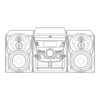
Step-by-step instructions for disassembling the main unit of the equipment.

Adjustment

Troubleshooting

Schematic Diagrams

Block Diagrams

Diagrams illustrating the functional blocks and signal flow of the system.

Standard Schematic Diagrams

Detailed circuit diagrams for various sections like amplifier and main boards.

Printed Circuit Board Layouts

Layout diagrams showing component placement on the main and amplifier printed circuit boards.

Related product manuals