1-7
RX-8022PSL
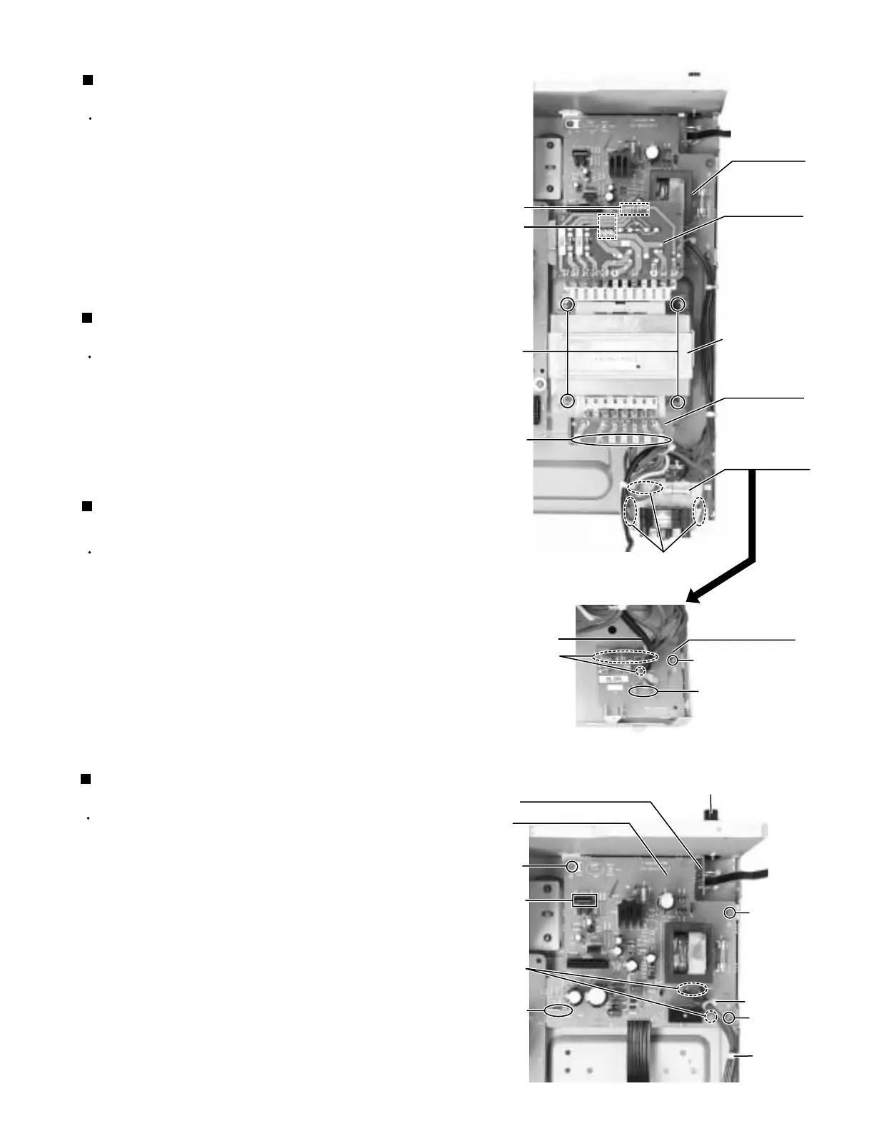
Prior to performing the following procedure, remove
the top cover and relay board.
Cut off the tie band if needed.
Disconnect the card wire from the connector CN402
on the power supply board.
Disconnect the harness from the connector
CN55/CN56 on the power trans1 board (see fig.17).
Remove the three screws W attaching the power
supply board and pull out the power supply board
removing the hook.
Unsolder the three solder parts on the power supply
board.
1.
2.
3.
4.
5.
Removing the power supply board
(See Fig.18)
Prior to performing the following procedure, remove
the top cover.
Removed the two screws G attaching the voltage
selector board to the rear panel (see fig.4).
Remove the screw H attaching the power/fuse board
to the rear panel (see fig.4).
Remove the screw V attaching the power/fuse board.
Unsolder the eight solder parts on the power/fuse
board.
1.
2.
3.
4.
Removing the power/fuse board
(See Fig.17)
Prior to performing the following procedure, remove
the top cover.
Removed the two screws G attaching the voltage
selector board to the rear panel (see fig.4).
Unsolder the six solder parts on the voltage selector
board.
1.
2.
Removing the voltage selector board
(See Fig.17)
Prior to performing the following procedures, remove
the top cover.
Disconnect the harness from the connector CN55
/CN56 and CN811 on the power trans1 board.
Unsolder the seven solder parts on the power trans2
board.
Remove the four screws U attaching the power
transformer.
1.
2.
3.
Removing the power transformer
(See Fig.17)
Fig.18
Headphone jack
Headphone jack board
Tie band
Solder part
(on the
reverse side)
Hook
Tie band
W
W
Power supply board
CN402
Fig.17
Power
supply board
CN55/CN56
CN811
Power
transformer
U
Solder part
Solder part
(on the reverse side)
Solder part
V
Power/fuse board
Power cord
Power
trans1 board
Power
trans2 board
Voltage
selector board
W
Solder part
(on the reverse side)
Under this board


 To Next Page