FS-SD1000R
1-15
Power woofer section
<Main body>
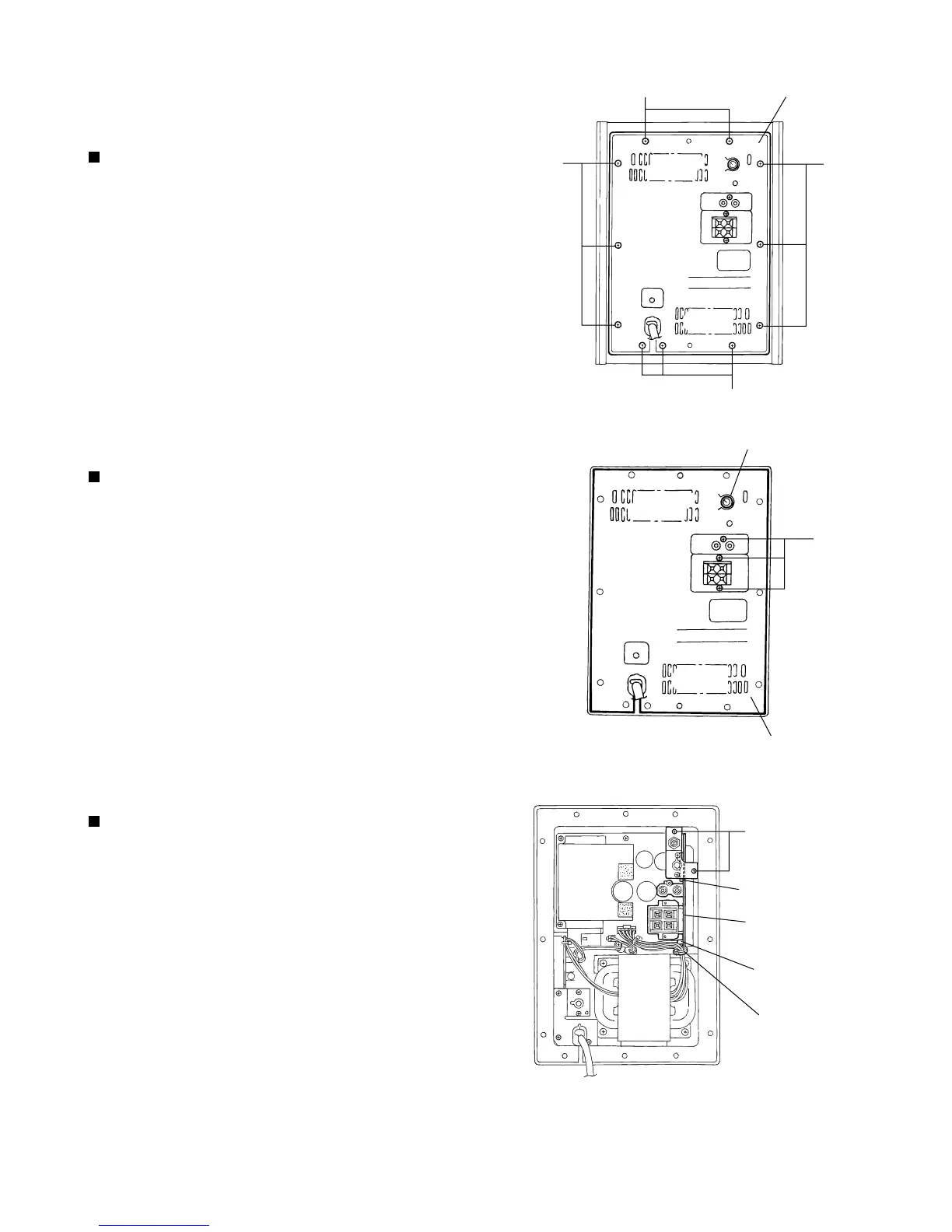
Removing the amplifier assembly
(See Fig.1)
Remove the eleven screws A attaching the amplifier
assembly on the back of the body.
Disconnect each relay harness connected to the
speaker and the LED indicator board.
1.
2.
Pull out the volume knob from the amplifier.
Remove the three screws B on the amplifier.
1.
2.
<Amplifier>
Removing the cover (See Fig.2)
Cut off the band under the input amplifier / filter
board assembly.
Disconnect the harness from connector CN251.
Remove the two screws C attaching the input
amplifier / filter board assembly. Pull and disconnect
connector CN211 from the body.
1.
2.
3.
Removing the Input amplifier / filter
board assembly (See Fig.3)
Fig.1
Amplifier board
A
A
A
A
Volume knob
Cover
B
Input amplifier / filter
board assembly
CN211
CN251
C
Band
Fig.2
Fig.3
 Loading...