(No.MB429)1-15
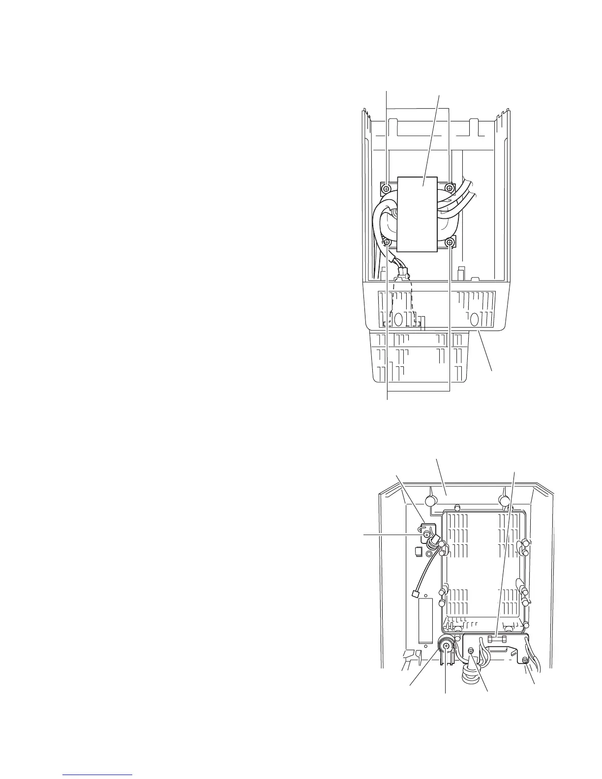
3.1.10 Removing the power transformer assembly
(See Fig.26, 27)
• Prior to performing the following procedure, remove the front
panel assembly and the power unit section.
(1) Remove the four screws F' attaching the power transform-
er assembly. The bracket comes off at the bottom of the
rear cover.
(2) Remove the screw G' attaching the power cord folder.
(3) Remove the two screws H' attaching the AC connect
board.
3.1.11 Removing the FM-ANT board
(See Fig.26, 27)
• Prior to performing the following procedure, remove the front
panel assembly and the power unit section.
(1) Remove the screw J' on the rear cover assembly.
(2) Unsolder the FM-ANT wire on the FM-ANT board.
Fig.26
Fig.27
Rear cover
F'
F'
Power trnsfomer assembly
Rear cover
FM-ANT board
G'
H'
H'
Power cord folder
AC connect board
J'
 Loading...