(No.MB057)1-27
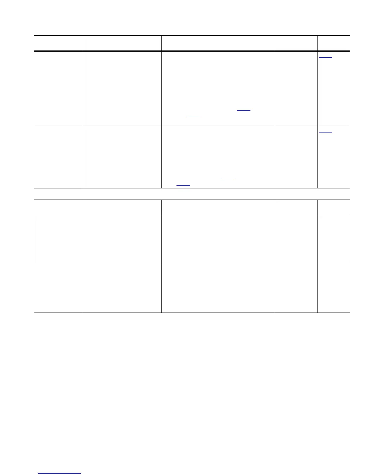
4.3.2 Electrical adjustment
4.3.3 Electrical response confirmation
Item Condition Measurement method Ref. value
Adjustment
position
Recording BIAS
adjustment
• Forward or Reverse
•Test tape
: AC-514 TYPE ll
: AC-225 TYPE l
• Output termina
Recording head
(1) Set the test tape(AC-514 TYPE ll and
AC-225 TYPE l), then make REC/
PAUSE condition.
(2) Connect 100Ω to recording head by se-
ries, then connect to VTVM for measure-
ment the current.
(3) After setting, start the recording by re-
lease the PAUSE, in this time bias cur-
rent adjust to next fig. by VR31
for Lch
and VR32
for Rch.
4.0 µA (TYPE ll) and 4.20 µA (TYPE l).
AC-225
: 4.20µA
AC-514
: 4.0µA
VR31
R/P playback
frequency
response
• Reference frequency
: 1kHz / 10kHz
(Reference: -20dB)
•Test tape
: AC-514 TYPE ll
• Input terminal
: OSC IN
(1) Set the test tape (AC-514 TYPE ), then
make REC/PAUSE condition.
(2) Release the PAUSE, then start recording
the 1kHz and 10kHz of reference fre-
quency from oscillator.
(3) Playback the recorded position, 1kHz
and 10kHz output deviation should -1dB
2dB to readjust by VR31
for Lch and
VR32 for Rch.
Output deviation
1kHz/10kHz
: -1dB ± 2dB
VR31
Item Condition Measurement method Ref. value
Adjustment
position
Recording bias
current
• Forward or Reverse
•Test tape
: TYPE ll (AC-514)
• Measurement terminal
: BIAS test point on printed
circuit board
(1) Change BIAS1 and 2, confirm the fre-
quency should be change.
(2) Set the test tape (AC-514 TYPE ll), then
make REC/PAUSE condition.
(3) Confirm the frequency should 100Hz ±
6kHz at BIAS test point on printed circuit
board.
100 kHz ± 6 kHz
Erase current (ref-
erence value)
• Forward or Reverse
• Rec condition
Test tape
: AC-514 TYPE ll
: AC-225 TYPE l
• Measurement terminal
Both side of Erase head
(1) Set the test tape (AC-514 TYPE ll and
AC-225 TYPE l), then make REC/
PAUSE condition.
(2) Release the PAUSE to REC condition,
connect 1W to ERASE head by series,
then confirm the erase current at both
side of erase head.
TYPE ll
: 120 mA
TYPE l
: 75 mA
 Loading...