The JVC SX-911WD is a high-fidelity speaker system designed for discerning audio enthusiasts. This service manual provides comprehensive details for its installation, operation, maintenance, and repair.
Function Description
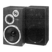
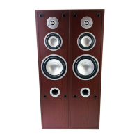
The SX-911WD is a 3-way, 3-speaker acoustic suspension type speaker system, available in distinct left (SX-911WDL) and right (SX-911WDR) configurations to ensure optimal stereo imaging. Each speaker cabinet houses a woofer, a midrange driver, and a tweeter, carefully integrated to reproduce a full range of audio frequencies with accuracy and clarity. The system is designed to be connected to an amplifier, with specific instructions for proper polarity and impedance matching to achieve the best performance.
Important Technical Specifications
- Type: 3-way, 3-speaker, acoustic suspension type.
- Speakers:
- Woofer: 305 mm (12") cloth carbon cone x 1.
- Midrange: 115 mm (4-1/2") cloth carbon cone x 1.
- Tweeter: 25 mm (1") amorphous-diamond coated dome.
- Power Handling Capacity: 150 watts (rated), 300 watts (music peak).
- Impedance: 6 ohms.
- Sensitivity: 91 dB, 1 W/1 m.
- Frequency Range: 40 Hz – 50 kHz.
- Crossover Frequencies: 500 Hz, 4000 Hz.
- Dimensions (W x H x D): 380 mm x 665 mm x 351 mm (15" x 26-3/16" x 13-7/8").
- Weight: 28.5 kg (63 lbs.) each.
- Accessory: Speaker cord 3m.
The speaker system's wide frequency range, extending from 40 Hz to 50 kHz, ensures the reproduction of deep bass and crisp, extended highs. The 6-ohm impedance is compatible with a wide range of amplifiers, with 6-ohm rated amplifiers recommended for optimal performance. The high sensitivity of 91 dB indicates that the speakers can produce significant volume with relatively low amplifier power.
Usage Features
- Stereo Configuration: The system consists of dedicated left (SX-911WDL) and right (SX-911WDR) speakers, which should be positioned accordingly for proper stereo imaging.
- Amplifier Connection: Connections are made via speaker cords to the amplifier's output terminals, ensuring correct polarity (+ to + and - to -).
- Power Handling Precautions: Users are advised to be mindful of the speaker's power handling capacity (150 watts continuous, 300 watts music peak) to prevent damage. Special attention is given to avoiding excessive input from certain signal types, such as interstation FM noise, high-frequency tape deck signals in fast forward, switching noise, cartridge changing noise, continuous high-frequency sounds from oscillators or musical instruments, and microphone howling.
- Digital Signal Reproduction: When playing digital signals from sources like CD players, caution is advised to ensure that peak values do not exceed the speaker's power handling capacity, given the fast rise time and wide dynamic range of digital audio.
- Front Grille: The front grille is magnetically attached, allowing for easy removal and reattachment. Users are cautioned to remove the grilles when moving the speakers to prevent damage and to avoid placing them near a TV set, as the magnets may cause color disturbance.
Maintenance Features
- Speaker Grille Removal: The front grille can be easily removed by pulling it towards the user, facilitating access to the speaker units.
- Speaker Unit Removal: The speaker units are mounted on the front panel and can be removed after the grille is taken off. When removing units, it is recommended to use felt or a soft cloth to prevent scratches on the cabinet, units, or terminals.
- Speaker Terminal Connections: For replacing old speakers or connecting to an existing system, the manual provides detailed instructions for preparing speaker cables (peeling shielding, inserting into holes) and securing them using a crimping jig or by wrapping and soldering.
- Woofer Unit Replacement (Left Speaker Only): For the left woofer unit, a specific Mylar capacitor is connected to the speaker terminals. When replacing the woofer, this capacitor should be cut and retained for future use.
- Crossover Network Access and Trimming: The crossover networks are located inside the rear board of the cabinet. Access requires removing all speaker units and then unscrewing the networks and terminals. The networks for left and right speakers are mounted in different positions, requiring careful attention during re-installation. Instructions are provided for trimming lead wires, which involves removing adhesive, cutting old wires, wrapping new wires, squeezing with pliers, soldering, and reapplying adhesive to secure the connection.
- Absorption Material: If sound-absorbing materials for the midrange unit and speaker cover are removed during repair or replacement, they must be reinstalled correctly as shown in the diagrams to maintain acoustic performance.
- Parts List and Schematic Diagram: The manual includes an exploded view and a comprehensive parts list for all components, along with a detailed schematic diagram of the crossover network, which is essential for troubleshooting and repair. This includes specifications for capacitors (N.P. Electrolytic, M.Paper) and coils, as well as other hardware.
The JVC SX-911WD is a robust and well-documented speaker system, designed for both high-quality audio reproduction and ease of serviceability.