1-8 (No.MB108)
3.1.4 Removing the front panel assembly
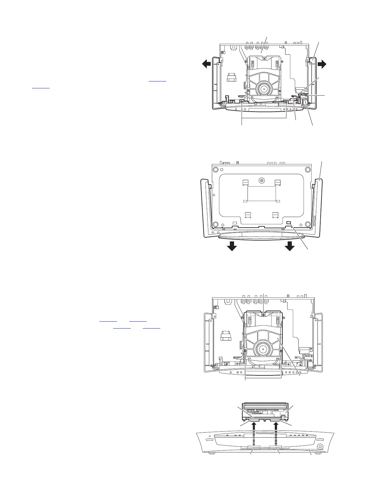
(See Figs.5 and 6)
• Prior to performing the following procedures, remove the top
panel.
(1) From the top side of the head phone board, remove the
three screws G attaching the front panel assembly. (See
Fig.5)
(2) Disconnect the card wires from the connectors CN408
and
CN412
on the main board. (See Fig.5)
(3) Extend the side of the front panel assembly in the direction
of the arrows a. (See Fig.5)
(4) Remove the front panel assembly in the direction of the ar-
rows c, while releasing the claw b. (See Fig.6)
Fig.5
Fig.6
3.1.5 Removing the DVD mechanism assembly
(See Figs.7 and 8)
• Prior to performing the following procedures, remove the top
panel and rear cover.
(1) From the top side of the main body, remove the two screws
H and screw J on the DVD mechanism assembly. (See
Fig.7)
(2) Disconnect the connectors CN502
and CN503 on the DVD
servo board from the connectors CN405
and CN406 on the
main board while lifting the DVD mechanism assembly up-
ward. (See Fig.8)
(3) Take out the DVD mechanism assembly from the main
board.
Fig.7
Fig.8
G
G
Front panel
assembly
aa
CN412
CN408
Head phone
board
Main board
Front panel
assembly
claw
b
c
c
H
J
DVD mechanism
assembly
CN503
CN502
CN406
CN405
DVD mechanism
assembly
DVD servo
board
Main board

 Loading...