EasyManuals Logo

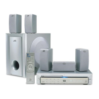
JVC TH-A5R Service Manual

JVC TH-A5R
80 pages
To Next Page IconTo Next Page
To Previous Page IconTo Previous Page
Page #25 background imageLoading...
Page #25 background image
TH-A5R
1-25
LC86P6548 (UIC1) : Microcontroller
1.Pin layout
S48/PG0
S49/PG1
S50/PG2
S51/PG3
P00
P01
P02
P03
VSS2
VDD2
P04
P05
P06
P07
P10/SO0
P11/SI0/SB0
P12/SCK0
P13/SO1
P14/SI1/SB1
P15/SCK1
S47/PF7
S46/PF6
S45/PF5
S44/PF4
S43/PF3
S42/PF2
S41/PF1
S40/PF0
VDD4
S39/PE7
S38/PE6
S37/PE5
S36/PE4
S35/PE3
S34/PE2
S33/PE1
S32/PE0
S31/PD7
S30/PD6
S29/PD5
S28/PD4
S27/PD3
S26/PD2
S25/PD1
S24/PD0
S23/PC7
S22/PC6
S21/PC5
S20/PC4
VP
P16/BUZ
P17/PWM0
P30
P31
P32
P33
P34
P35
P36
P37
P70/INT0
RES
XT1/P74
XT2/P75
VSS1
CF1
CF2
VDD1
P80/AN0
P81/AN1
P82/AN2
P83/AN3
P84/AN4
P85/AN5
P86/AN6
P87/AN7
P71/INT1
P72/INT2/T0I
P72/INT3/T0I
S0/T0
S19/PC3
S18/PC2
S17/PC1
S16/PC0
VDD3
S15/T15
S14/T14
S13/T13
S12/T12
S11/T11
S10/T10
S9/T9
S8/T8
S7/T7
S6/T6
S5/T5
S4/T4
S3/T3
S2/T2
S1/T1
81
82
83
84
85
86
87
88
89
90
91
92
93
94
95
96
97
98
99
100
50
49
48
47
46
45
44
43
42
41
40
39
38
37
36
35
34
33
32
31
80
79
78
77
76
75
74
73
72
71
70
69
68
67
66
65
64
63
62
61
60
59
58
57
56
55
54
53
52
51
1
2
3
4
5
6
7
8
9
10
11
12
13
14
15
16
17
18
19
20
21
22
23
24
25
26
27
28
29
30
2.Block diagram
Interrupt Control
A15-A0
D7-D0
TA
CE
OE
DASEC
Standby Control
Clock
Generator
CF
RC
X tal
Base Time
r
SIO0
SIO1
Timer 0
Tim
er 1
ADC
INT0-3
Noise Filt er
SIO Auto
matic
transmission
RAM
128 by
te
s
VFD
Controller
High voltage Output
Bus Interface
Port 1
Port 3
Port 7
Port 8
IR PLA
PROM
Control
PROM(48KB)
PC
ACC
B Register
C Register
A
LU
PSW
RAR
RAM
Stack Poi nter
Port 0
Watchdog Timer

Other manuals for JVC TH-A5R

Questions and Answers:

Question and Answer IconNeed help?

Do you have a question about the JVC TH-A5R and is the answer not in the manual?

JVC TH-A5R Specifications

General IconGeneral
BrandJVC
ModelTH-A5R
CategoryHome Theater System
LanguageEnglish

Related product manuals