(No.MB427)1-33
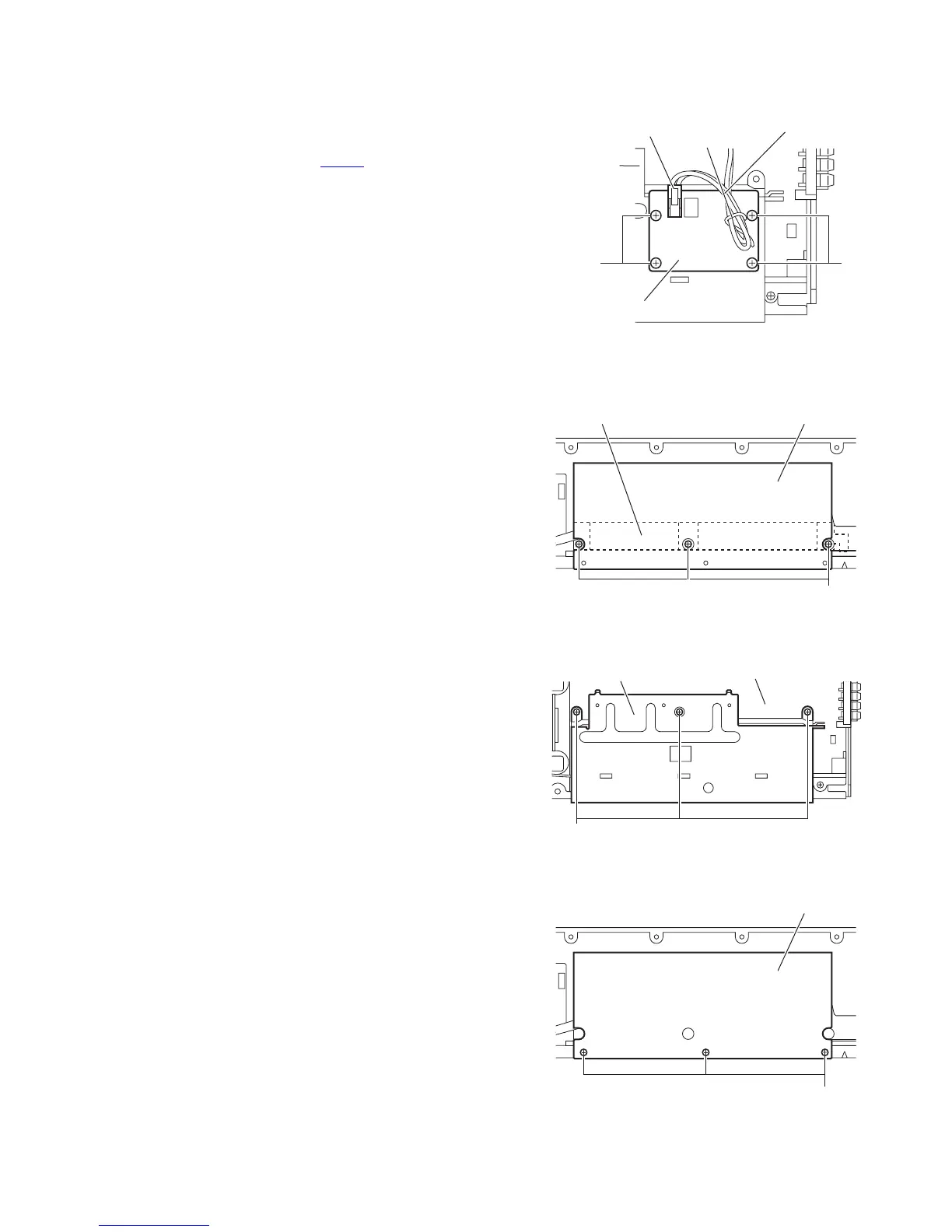
3.4.5 Removing the relay board
(See Fig.10)
• Prior to performing the following procedure, remove the ampli-
fier assembly.
(1) From the top side of the amplifier assembly, disconnect the
parallel wire from the connector CN352
on the relay board.
(2) Remove the four screws J attaching the relay board to the
heat sink.
(3) Take out the relay board.
Reference:
After attaching the relay board, bundle the parallel wire by wire
clamp.
Fig.10
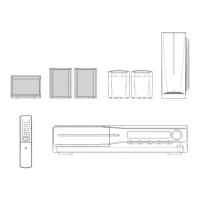
3.4.6 Removing the heat sink
(See Figs.11 and 13)
• Prior to performing the following procedures, remove the am-
plifier assembly, rear panel, power board and relay board.
(1) From left side of the amplifier assembly, remove the three
screws K attaching the IC bracket to the heat sink. (See
Fig.11.)
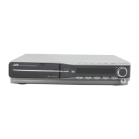
(2) Remove the three screws M attaching the heat sink to the
main board. (See Fig.12.)
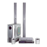
(3) From left side of the amplifier assembly, remove the three
screws N attaching the heat sink. (See Fig.13.)
(4) Take out the heat sink.
Fig.11
Fig.12
Fig.13
Relay board
Wire clamp
Heat sink
CN352
Parallel wire
JJ
K
Heat sinkIC bracket
Heat sink
Main board
M
N
Heat sink