(No.MB211)1-9
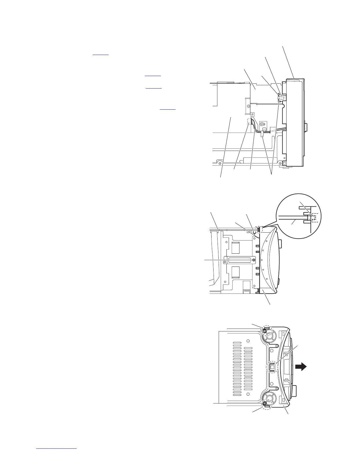
3.1.2 Removing the front panel assembly
(See Figs.4 to 6)
• Remove the metal cover.
(1) From the left side of the main body, disconnect the wire
from the connector CN104
on the power supply board.
(See Fig.4.)
Reference:
After connecting the wire to the connector CN104
, fix the
wire with the spacer as before. (See Fig.4.)
(2) Disconnect the card wire from the connector CN700
on the
micon board. (See Figs.4 and 5.)
Reference:
After connecting the card wire to the connector CN700
,
fix the card wire with the spacer as before. (See Fig.4.)
(3) From the top side of the main body, remove the screws C
attaching the front panel assembly. (See Fig.5.)
(4) From the bottom side of the main body, remove the two
screws D attaching the front panel assembly. (See Fig.6.)
(5) Release the two claws a and claw b from the both and bot-
tom sides of the front panel assembly, and remove the front
panel assembly in the direction of the arrow. (See Fig.6.)
Reference:
When attaching the front panel assembly, fit the micon board
to the notch c on the back side of the front panel assembly.
(See Fig.5.)
Fig.4
Fig.5
Fig.6
Front panel assembly
Spacer
Power supply board
CN104
Micon board
CN700
Card wire
Wire
C
Micon board
c
Micon board
Front panel assembly
CN700
Card wire
D
Front panel assembly
a
b
a
 Loading...