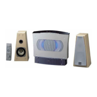
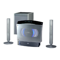
VS-DT2000
1-23
1. Terminal layout
MN101C35DKB (IC811) : FL driver microcomputer
1
25
75
51
100 76
26 50
2. Pin function
1
2
3
4
5
6,7
8
9
10
11,12
13
14 23
24
25
26
27 30
31
32
33 38
39,40
41
42
43
44 46
47
48 60
61
62 64
65 99
100
NC
FLDATA
FLCLK
NC
FLCS
NC
B5V
OSC2
OSC1
GND
NC
GND
VREF
NC
FLRST
NCV70
REMCON_HO
NCV70
GND
NCV70
KEYLEDH
KEYLEDV
KEYDIMMER
NC
G1
G2 G14
G15
S1 S35
-VPP
-
I/O
I
-
I
-
-
O
I
-
-
-
-
-
I
-
O
-
-
-
-
-
-
-
-
O
-
-
O
-
Not connect
FL driver communication data input/output
FL driver communication clock input
Not connect
FL driver communication chip select input
Not connect
VDD(B5V)
8MHz main clock output
8MHz main clock input
Ground
Not connect
Ground
Reference voltage
Not connect
FL reset input
Not connect
Switching signal for receiver part of remote controller
Not connect
Ground
Not connect
Not use
Not use
Not use
Not connect
Not connect
Grid signal outputs
Not connect
Not connect
Segment signal outputs
VPP
Pin No. Symbol I/O Function
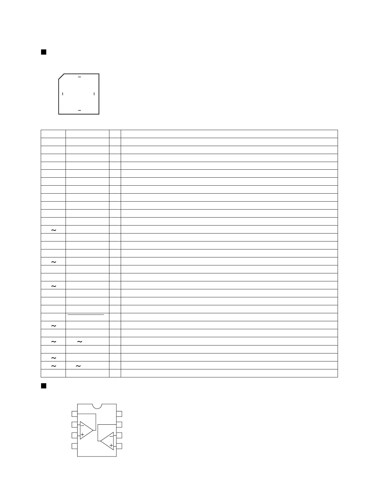
1. Terminal layout & Block diagram
1
2
8
7
6
5
1
2
3
4
OUT1
IN1-
IN1+
VEE
Vcc
OUT2
IN2-
IN2+
Description of major ICs
BA15218F (IC102) : Dual operational amplifier
 Loading...