VS-DT2000
1-15
Fig.7
Fig.8
Fig.9
Section f
Groove g
Groove h
Traverse mechanism assembly
Spindle motor
Feed motor
Red
Red
Black
Traverse
mechanism board
H
J
H
Section j
Rack prate
E
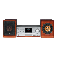
Attaching the pickup unit
(See Figs. 7 and 8.)
1.
2.
3.
4.
Attach the P.S. spring and rack plate to the pickup
unit.
Insert the shaft into the pickup unit.
Engage the section f of the pickup unit with the
traverse mechanism assembly first, and set the
both ends of the shaft in the grooves g and h.
After making sure that the section j of the rack plate
is meshed correctly with the middle gear, attach the
shaft using the two screws E.
[Reference]
Refer to the explanation of "Removing the
pickup unit" on the preceding page.
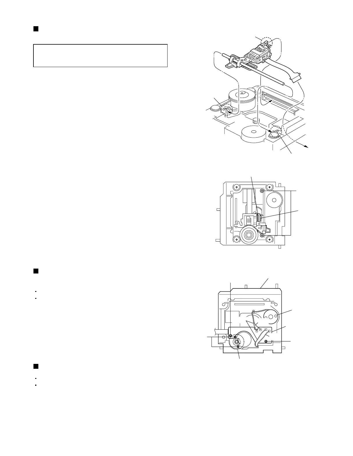
Removing the traverse mechanism
board (See Fig. 9.)
1.
2.
Remove the CD servo board.
Remove the traverse mechanism assembly.
From the back side of the traverse mechanism
assembly, disconnect the spindle motor wires and
feed motor wires that are soldered on the traverse
mechanism board.
Remove the two screws H attaching the traverse
mechanism board.
Removing the feed motor (See Fig. 9.)
1.
2.
Remove the CD servo board.
Remove the traverse mechanism assembly.
From the back side of the traverse mechanism
assembly, disconnect the feed motor wires that are
soldered on the traverse mechanism board.
Remove the two screws J attaching the feed motor.
 Loading...