The K2 Splice Foot X & XL is a component designed to support photovoltaic (PV) systems, specifically for mounting solar rails onto various roof types. This quick guide outlines the installation process, tools required, and important considerations for both rafter and deck connections.
Function Description:
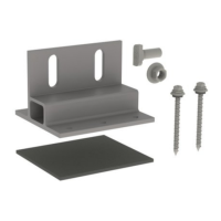
The Splice Foot X & XL serves as a versatile roof attachment for solar racking systems, facilitating the secure mounting of rails to a roof structure. It is designed to connect either a single CrossRail or to splice two rails together, providing a stable foundation for solar modules. The system is compatible with both rafter-attached and deck-attached installations, offering flexibility based on the roof's structural characteristics and mounting zone requirements. The design incorporates features for proper sealing and alignment, ensuring a durable and watertight installation.
Important Technical Specifications:
- Part Numbers:
- 4000113: Splice Foot X, Kit, Mill
- 4000162: Splice Foot XL, Kit, Mill
- Mounting Type: Rafter-attached or Deck-attached.
- Fasteners: Lag screws (for rafter connection) and Splice Foot screws (for deck connection).
- Torque Specifications: T-Bolt tightening to 25.8 ft-lbs (35 Nm).
- Material: The "Mill" designation in the part numbers likely refers to the finish or material type, typically unanodized aluminum for structural components in solar racking.
- Rail Compatibility: The rail connector function for the Splice Foot is specifically compatible with "mill rail," indicating a particular type or finish of K2 CrossRail.
- Sealing: Utilizes butyl sealant and compatible roof sealant to ensure waterproofing.
Usage Features:
- Versatile Mounting: Can be installed directly into rafters for maximum structural integrity or onto the roof deck (plywood) as a secondary option when rafters are not within the optimal mounting zones.
- Rafter Connection: Involves driving two lag screws through the center holes of the Splice Foot base into the rafter. The conical washer on the lag screw provides a positive seal upon stopping rotation.
- Deck Connection: Requires four Splice Foot screws to be installed into all four corners of the mount base, ensuring positive engagement into the plywood and avoiding plywood seams. This method should be used in accordance with K2 engineered calculations and span charts.
- Rail Attachment:
- Single CrossRail: A single T-Bolt is inserted through one Splice Foot slot and into the side channel of the CrossRail. Proper alignment is indicated by a vertical mark at the end of the T-Bolt shaft.
- Splicing Two Rails: Two T-Bolts are used, one for each rail, inserted through the Splice Foot slots. A 5/8" gap must be maintained between the two rails in the center of the Splice Foot for proper splicing.
- Chalk Line and Measurement: Installation begins with marking the array layout on the roof using a chalk line to define rail locations within shingle courses and mounting locations over rafters. A tape measure is used for precise placement.
- Leveling Uneven Roof Surfaces: For roofs with uneven surfaces, an additional piece of K2 butyl or a standard composition shingle starter course can be used to level the area under the Splice Foot, ensuring a flat and stable base.
- Patent Pending: The "Patent Pending" status indicates ongoing innovation and unique design aspects of the Splice Foot X & XL.
Maintenance Features:
While the manual primarily focuses on installation, the design implicitly supports long-term durability and minimal maintenance through:
- Robust Sealing: The use of butyl and compatible roof sealants at installation points is crucial for preventing water ingress, a common source of roof and system damage. Proper sealing at the top and side edges of the mount, covering exposed butyl, and sealing shingle seams within 2 inches of lag screws contribute to a watertight system, reducing the need for future leak repairs.
- Durable Materials: Although not explicitly detailed, K2 Systems typically uses corrosion-resistant materials like aluminum for its racking components, which inherently reduces the need for frequent maintenance due to rust or material degradation.
- Proper Torque Specifications: Adhering to the specified torque for T-Bolts (25.8 ft-lbs / 35 Nm) ensures that connections remain secure over time, preventing loosening due to environmental factors like wind uplift or thermal expansion/contraction, thereby reducing the need for re-tightening.
- Structural Integrity: The emphasis on proper rafter or deck attachment, guided by engineering letters and span charts, ensures the system's structural integrity, minimizing the risk of component failure and subsequent maintenance. Regular inspections of the system, particularly after severe weather events, would be the primary maintenance activity to ensure all components remain secure and sealed.
- Chalk Line
- Tape Measure
- Compatible Sealant
- 8mm hex socket or Phillips head (for screws)
- 13mm socket (for T-Bolts)
Important Notes for Installation:
- Always inspect and qualify the roof type and condition for appropriate use of structural attachment and waterproofing products.
- The installer is responsible for choosing compatible, code-compliant products.
- Refer to module manufacturer frame clamping zones for rail location.
- Refer to engineering letters for allowable mount spacing.
- Do not over-torque lag screws; stop when the conical washer stops rotating.
- For deck attachments, follow K2 engineered calculations and span charts.
- When deck attaching, check for positive engagement into plywood and avoid plywood seams.
- Ensure proper T-Bolt alignment (vertical mark on shaft) for secure rail connection.
- Maintain a 5/8" gap between rails when splicing.
For additional resources, K2 Systems provides a "base-camp" website and technical support via phone. A video on mount leveling is also available on their YouTube channel.