5
Saflok SR
TM
Series RFID Reader Installation Guide - PK3670_T_08_15
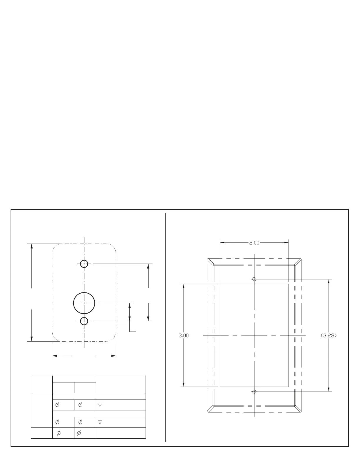
1-11/16
[42,9]
17/32
[13,5]
1-7/8
[47,6]
2-7/8
[73]
A
A
B
HOLE
ID
DIM
COMMENTS INCH[mm]
INCH [mm]
A
INSTALLATION WITH DRYWALL INSERT
7/32 5,6 1-1/2 [38,1]
INSTALLATION WITH METAL SCREW
9/64 3,6 1/2 [12,7]
B
5/8 15.9-
2- Installing the Saflok SR RFID RCU
SR1 Surface Mount installation SR2 Flush Mount installation
Note: The SR RFID RCU Controller is optionally provided with a plastic double-gang deep switch box intended for
interior installations. Please check your local building codes before installing.
1. Position the reader box in an accessible location on the locked side. The box should be in close proximity to the
access opening as the user will have five seconds to open the door before it relocks. For exterior applications
the surface mount sealed SR1 unit shall be used. Use the drilling template below to prepare the wall or metal
door frame for attaching the SR1 back plate.
2. Position the controller box on the opposite side of the wall within 15 meters of the reader.
3. Run the appropriate wires to the controller enclosure and SR reader enclosure in accordance with the schematic
diagram on the following page. For connecting the reader to the controller 3 twisted pair x 22 AWG CMP cable
is recommended (Belden 6542FE, or equivalent). Ensure compliance with local building codes.
4. Make the necessary wire connections in accordance with the schematic diagram on the following page.
5. Secure the faceplate to the controller box with the four #6-32 x 1” screws (provided). For the SR2 flush mount
reader, secure the faceplate to the reader box with the two #6-32 x 1” screws (provided). Tighten the screws
using the 5/64” Allen wrench (provided). For the SR1 surface mount, hang the reader housing on the back plate
clip, swing down into position, and fasten with #8-32 screw (provided) through hole in bottom of case.
6. Program the RCU/ECU by using the propertys hand held programmer. Connect the USB probe to the USB port
located on the serial interface board located in the controller box.
 Loading...