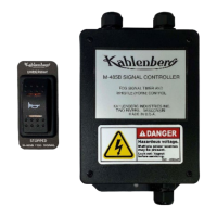
The Kahlenberg Model M-485B Horn Signal Controller is a solid-state device designed for automating sound signals on vessels, specifically for conditions of restricted visibility (fog signals) as prescribed by International Navigation Rules (IMO) COLREGS Part D, Rule 35. It is manufactured by Kahlenberg Industries, Inc.
Function Description:
The M-485B serves as a comprehensive horn signal controller, fog signal timer, and whistle control unit. Its primary function is to generate the required horn signals for vessels in restricted visibility, ensuring compliance with international maritime regulations. The unit is capable of outputting signals for vessels "Underway" and "Underway but stopped," as well as for motor and sailing vessels, according to IMO "COLREG 72" and COMDTINST M16672.2D.
The controller is designed to activate either an electric solenoid valve (for air horns) or a 12 or 24 Volt D.C. Electric Horn. It comes pre-configured from the factory to activate an electric solenoid valve that matches the supply voltage of the M-485B (12 or 24 Volt D.C.). However, it can be internally reconfigured to activate a 12 or 24 Volt D.C. Electric Horn.
The M-485B produces the following signal codes:
- One Long Blast (4-6 seconds): For a power-driven vessel making way through the water, sounding at intervals of not more than 2 minutes.
- Two Long Blasts (4-6 seconds each): For a power-driven vessel underway but stopped and making no way through the water, sounding at intervals of not more than 2 minutes, with two prolonged blasts in succession with an interval of about 2 seconds between them.
- One Long and Two Short Blasts: For a vessel not under command, a vessel restricted in her ability to maneuver, a vessel constrained by her draught, a sailing vessel, a vessel engaged in fishing, or a vessel engaged in towing or pushing another vessel. This signal is sounded at intervals of not more than 2 minutes, consisting of one prolonged blast followed by two short blasts.
The unit includes an illuminated M-129 two-position panel rocker switch for user interaction.
Important Technical Specifications:
- Power Requirements: 12-24 Volts D.C., +30%, -10%.
- Maximum Current Required: 2 Amps @ 12 Volts.
- Output Relay:
- Max. Switching Current: 5 Amps @ 30 Volts D.C.
- Rated Carry Current: 10 Amps.
- Ingress Protection:
- IP66 (M-129 Switch assembly only)
- IP 60 Enclosure
- Weight: 1 lbs (0.45 kg).
- Dimensions: 7.29" x 4.34" x 1.85″ (186 x 111 x 47mm).
- Installation Environment:
- Protected from weather, code B, IEC60945 (Enclosure Only)
- Exposed to weather, code C, IEC60945 (Switch Assembly Only)
Important Note on Compressor Compatibility: The M-485B CANNOT be connected directly to air horns powered by small rotary "bean can" compressors. These compressors draw high amperage (over 10 amps), which will permanently damage the M-485B controller.
Usage Features:
The M-485B is designed for straightforward operation through the M-129 Rocker Switch.
- Initial Setup (Vessel Type): The unit has an internal jumper (J2) on the circuit board that determines the restricted visibility codes for "MOTOR" or "SAIL" vessels. The unit ships configured for "MOTOR" vessels. To change to "SAIL" vessel codes, the jumper must be gently pulled off its pins and moved to disconnect the jumper circuit. The unit must be re-powered for this change to take effect.
- Installation: The M-485B enclosure should be installed in a weather-protected location, typically inside the main control console, within approximately 2-1/2 feet of the intended switch location. The M-129 Rocker Switch is installed in the P548-04 mounting bezel, which fits into the console switch panel. The bezel accommodates panel material thicknesses from .062" (1.57mm) to .375″ (9.52 mm).
- Electrical Connections:
- Air Horn Solenoid Valve: If connecting to an air horn solenoid valve of the same voltage, internal connections are factory-made to use the incoming M-485B main power for the internal relay. Connections are made according to wiring diagrams 3-7584 or 3-7577 (if an M-130 "at will" horn switch is also used).
- Electric Horn (12 or 24 Volt D.C., Max. 10 Amps @ 12 volts D.C.): For electric horns, the M-485B enclosure must be opened, the red jumper wire between terminal blocks J1 and J8 removed, and the black horn cable wire moved from the 4th terminal location on J1 to the 3rd terminal location on J8 (next to the existing red horn cable wire). Connections are made according to wiring diagrams 3-7597 or 3-7582 (if an M-130 "at will" horn switch is also used).
- Operation via M-129 Switch:
- "Underway" Position: Moving the switch to "Underway" illuminates the amber LED. For a "Motor Vessel" setting, the horn sounds one long blast (approx. 4 seconds) and repeats every two minutes. For a "Sail Vessel" setting, the horn sounds one long blast followed by two short blasts, repeating every two minutes.
- "OFF" Position: Moving the switch to the center "OFF" position turns off the LED and stops horn sounding.
- "Stopped" Position: Moving the switch to the bottom "Stopped" position illuminates the amber LED. The horn sounds two long blasts (approx. 4 seconds each) and repeats every two minutes.
- "At-Will" Horn Button Integration: When an "At-Will" horn button (such as the Kahlenberg M-130 Horn Button) is pressed while the M-485B is operating in "Stopped" or "Underway" modes, the horn will sound. If using the M-130 button, the M-485B Controller will temporarily stop the automated signal pattern, and the LEDs on the switch will flash to indicate interruption. To reset, the rocker switch must be moved to the "Off" position. If a standard single pole "At-Will" switch is used, the horn will sound when depressed, but the automated signal code from the M-485B will continue uninterrupted.
Maintenance Features:
- Non-User Serviceable: The M-485B is a solid-state unit and is not user serviceable. For any replacement parts or assistance, users should contact Kahlenberg Industries with the model and serial numbers of the unit.
- Troubleshooting: A troubleshooting guide is provided to address common issues such as the unit not functioning (blown fuse, incorrect wiring), horn not sounding despite current (solenoid valve voltage mismatch, incorrect installation), or incorrect signal sounding (incorrect wiring causing PCB resets).
- Storage: For extended storage, the M-485B should be kept indoors at temperatures above 32°F (0°C). It should be placed in a poly bag with silica desiccant packets to protect it from dust and excessive moisture.
- Safety: Important safety instructions emphasize the danger of electric shock. Users are warned not to service the product in wet conditions or with wet hands/feet. It is crucial to ensure sufficient electrical supply and to always remove and lock out/tag out electrical power before performing any maintenance.