VDCF03.01GB
Workshop Manual DCF 90-100
7 Load handling – 7.8 Levelling 65
7.8 Levelling
page –
Mechanical levelling, function description
Mechanical levelling is possible because the attachment’s main beam
is movably suspended over the slide plates in the main beam. A lateral
clearance allows for mechanical levelling ±3°. Mechanical levelling
means that the attachment is in a float position and adapts to the angle
of the container to be lifted.
page –
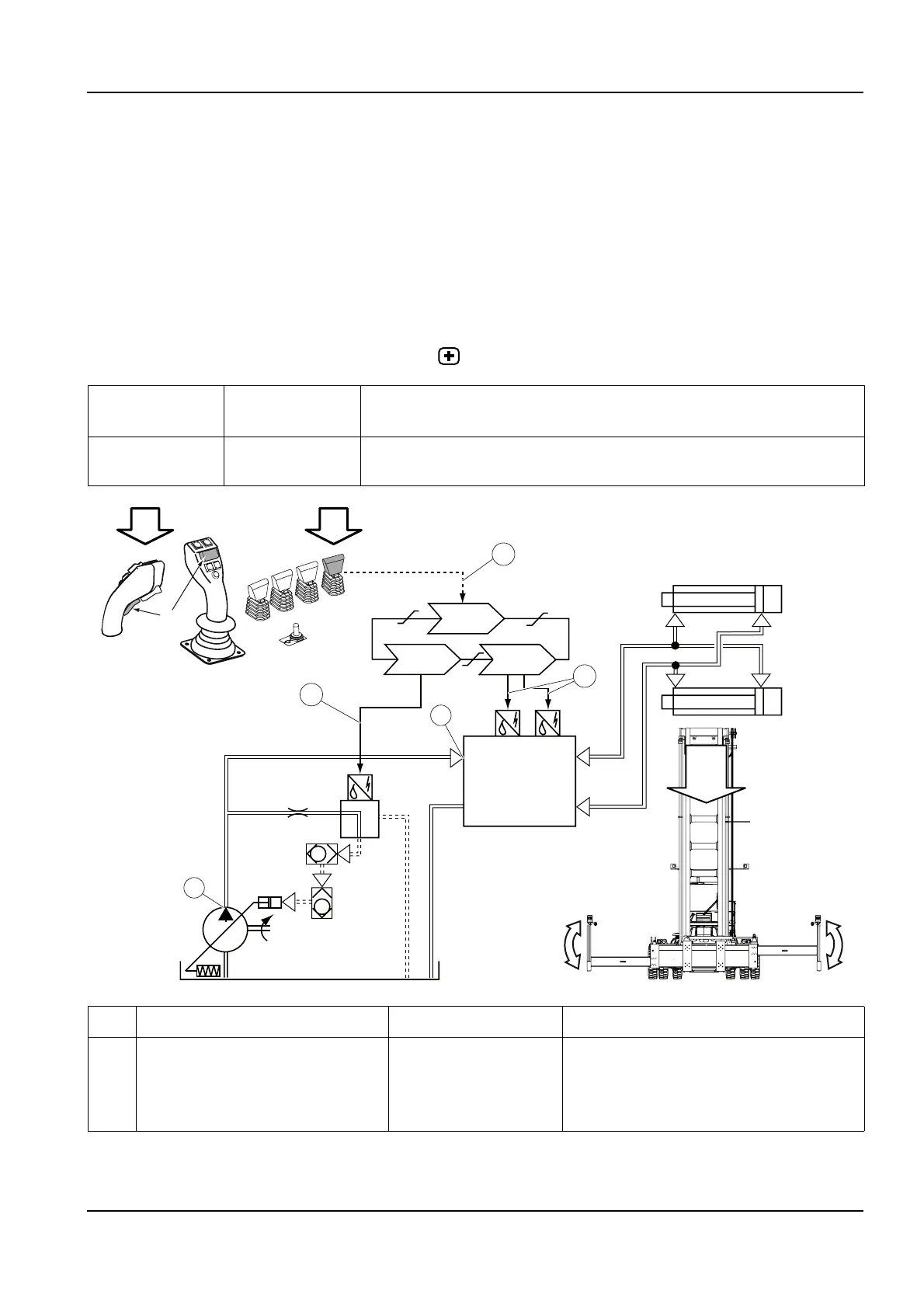
Active levelling, function description
Condition Reference
value
Reference
Emergency stop
switch
Not activated Section 11 Common electrics, group 11.5.1.4 Emergency stop switch voltage
D790-1
D797-1
009348
D791-1
11
11
10
8
7
5
6
4
3
2
P1
T1
A
B
9
C
1b
+
1a
D1
D2
D3
C
Pos Explanation Signal description Reference
1a The levelling control lever (R8075-1-
P5) sends a voltage signal to the cab
control unit (D790-1).
U = 0.5-4.5 V
Left: U = <2.5 V
Right: U >2.5 V
Control levers for electric servo, description
page 5
D1: Diagnostic menu, see section 8 Control
system , group 8.4.9.2 ATTACH, menu 2