The provided manual describes the KAMA KM376 Series Three-Cylinder Water-Cooled Diesel Engine, manufactured by Wuxi Kama Power Co., Ltd. This operation manual covers safe information, operation instructions, and maintenance procedures to ensure the engine operates at its best working condition.
Function Description
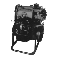
The KAMA KM376 series is a range of three-cylinder, water-cooled diesel engines designed for various applications. These engines utilize an in-line, 4-stroke combustion cycle with a swirl-type combustion chamber. The manual emphasizes the importance of proper operation and maintenance for the engine's longevity and reliable performance. The engine incorporates a 12V DC electric start system and a pressure and splash lubricating system. Fuel injection is managed by a VE distributor pump with a dual-function throttling pintle nozzle. Cooling is achieved through a centrifugal water pump.
Important Technical Specifications
The KM376 series includes models KM376QC, KM376G, and KM376AG, with slight variations in specifications:
General Engine Data:
- Type: In-line, 4-stroke, water-cooled (KM376AG is Tilt, 4-stroke, water-cooled).
- Combustion Chamber Type: Swirl type.
- Cylinder No.: 3.
- Fire Order (from free end): 1-2-3.
- Compression Ratio: 21.5.
- Rotation Direction (facing flywheel): Counterclockwise.
- Starting System: 12V DC electric start.
- Lubricating System: Pressure and splash.
- Overall Dimension (L×W×H): 594×451×623 mm.
- Net Weight: <110 kg for all models.
Model-Specific Data:
- KM376QC:
- Bore x Cycle: 76×73 mm.
- Piston Displacement: 0.993 L.
- Rated Power: 25 kW.
- Rated Speed (15 minutes power): 3000/3600 r/min.
- Max Torque/Speed: 54 N.m / 3200 r/min.
- Min Fuel Consumption at Max Throttle: 312 g/kW.h.
- KM376G:
- Bore x Cycle: 76×77 mm.
- Piston Displacement: 1.048 L.
- Rated Power: 18.7/20.6 kW.
- Rated Speed (15 minutes power): 3000/3600 r/min.
- Max Torque/Speed: 56 N.m / 3000 r/min.
- Min Fuel Consumption at Max Throttle: 300 g/kW.h.
- KM376AG:
- Bore x Cycle: 76×77 mm.
- Piston Displacement: 1.048 L.
- Rated Power: 19.5/23 kW.
- Rated Speed (15 minutes power): 3000/3600 r/min.
- Max Torque/Speed: 62.5 N.m / ≤3000 r/min.
- Min Fuel Consumption at Max Throttle: 300 g/kW.h.
Common Performance Data:
- Max Steady Speed at Zero-load: 5800±150 r/min.
- Idle Speed: 900±50 r/min.
- Lube Oil/Fuel Consumption Ratio at Full Speed and Full Load: ≤0.8%.
- Exhaust Smoke FSU: 4.4.
Key Parts Specifications:
- Fuel Injection Pump: VE distributor pump (Model VE3/9F2500LND), 9mm plunger diameter, mechanical full-length governor.
- Fuel Injector: S series (P series) thread coupling, dual-function throttling pintle nozzle, fuel delivery pressure 13.5~14.5 Mpa, working speed 2500 r/min.
- Lube Oil Pump: Working pressure 249 Kpa, flow volume above 20 L/min.
- Cooling Water Pump: Centrifugal type, speed 5000 r/min, flow volume 55 L/min.
- Lube Oil Filter: Screw-in type.
- Generator: Silicon rectifying, parallel excitation, 14V voltage, 40A (45A in cold area) rated current.
- Starter Motor: DC motor, 12V voltage, 1.4kW power.
- Glow Plug: 11V working voltage, 7-8 seconds working time, above 750°C working temperature.
- Thermoregulator: Paraffin type.
- Diesel Oil Filter: Paper element (with fuel/water separator and portable pump).
Adjusting Data Table:
- Non-compression space height inside cylinder: 0.7-1.0 mm.
- Fuel Delivery Timing: Piston at upper dead point, fuel pump plunger stroke 0.97±0.03 mm or 0.89±0.03 mm.
- Fuel Spraying Pressure: 13.5-14 Mpa (green) and 14.1-14.5 Mpa (pink).
- Valve Open/Close Phase: Intake opens at BTDC16°±10°, closes at ABDC40°±10°; Exhaust opens at BBDC52°±10°, closes at ATDC14°±10°.
- Valve Clearance (cold state): Intake 0.25±0.05 mm, Exhaust 0.3±0.05 mm.
- Valve (intake&exhaust) joint ring width: 1.2-1.6 mm.
- Valve Sunk Volume: 0.7-1 mm.
- Belt Tension: Press down 6-7 mm with 10 kg pressure (new belt: 5-6 mm).
- Lube Oil Pressure: 0.4-0.6 Mpa, idle speed ≥0.15 Mpa.
- Lube Oil Temperature: 60°C-110°C.
- Drained Water Temperature: <95°C.
- Exhaust Temperature: <750°C.
Tightening Torques:
- Cylinder head bolt: M12×1.25, 90+10 Nm.
- Camshaft bearing bolt: M8, 16+1 Nm.
- Main bearing bolt: M10×1.25, 60+5 Nm (Turbocharger-type: M12×1.25, 85±5 Nm).
- Oil sump bolt: M6, 5.5+1.5 Nm.
- Connecting rod bolt: M9×1.0, 47+5 Nm.
- Flywheel bolt: M10×1.25, 55±5 Nm.
- Thread of fuel injector body: M20×1.25, 60±10 Nm.
- Glow plug thread: M10×1.25, 12±2 Nm.
- Other bolts and nuts: M6 (7.5±1.5 Nm), M8 (18.5±3.5 Nm), M10×1.25 (37.5±7.5 Nm), M12×1.25 (60±10 Nm).
Usage Features
The manual provides detailed instructions for preparing, starting, running, and stopping the engine, along with specific considerations for different environmental conditions.
Preparation before Operation:
- Fuel: Use recommended light diesel oil (JIS K2204 / GB252-87) appropriate for ambient temperature. Emphasizes using clean fuel and avoiding contamination.
- Lubricating Oil: Use L-ECD grade oil (15W/30 or 15W/40). Store and use carefully to avoid dust and impurities. Do not mix different types of lubricating oil.
- Cooling Water: Use tap water. In winter, add anti-freezing solution (30-55% mixing ratio) or anti-rusting solution (6% mixing ratio) in other seasons. Proper mixing ratio is crucial to prevent freezing or decreased engine performance.
- Fluid Levels: Ensure lubricating oil and cooling water levels are sufficient before starting.
- Air Elimination: Crucial to eliminate air from the fuel system (low-pressure and high-pressure lines) after refilling fuel or for first-time use, as air can prevent the engine from starting.
- Battery Check: Verify battery electrolyte level monthly and refill with distilled water if low. Check density with a gravity meter; if below 1.24 g/ml, recharge or replace. Ensure proper connection of the negative lapping iron.
Starting the Engine:
- No Load: Start the engine under no load.
- Throttle Position: Set the throttle lever at the half-open position.
- Electric Start Procedure: Insert key, turn to ON (glow plug indicator lamp lights for 7-8 seconds, then goes out), then turn to START. Release key, and it returns to ON.
- Start Duration: Do not use the start switch for more than 15 seconds at a time. Wait 1 minute before restarting if the engine doesn't start.
- Cold Start: Below 5°C, warm up intake gas, fuel, cooling water, or lube oil, or use solvent to aid starting.
Running the Engine:
- Warm-up: After starting, run at idle speed for about 5 minutes, then transition to medium-speed, small-load running. Gradually increase load and rotary speed as engine temperature rises.
- Avoid Sudden Changes: Do not suddenly increase or decrease rotary speed or load.
- Monitoring: Regularly inspect engine oil pressure and temperature, cooling water temperature, and charging indicator. Observe exhaust gas color and listen for abnormal sounds.
- Abnormalities: Stop the engine immediately if oil pressure is too low, cooling water temperature is too high, dense smoke is exhausted, or knocking sounds occur.
- Resonance Range: Avoid running the engine in its resonance range to prevent excessive vibration and damage.
- Winter/Summer Operation: Provide adequate heat preservation in winter and cooling measures in summer.
- Overload: Avoid prolonged operation under overload to prevent damage and shorten service life.
Stopping the Engine:
- Gradual Decrease: Gradually decrease engine speed to idle.
- Cooling Down: Allow the engine to stop only when cooling water temperature is below 70°C.
- Switch Off: Turn the starter switch key to OFF.
- Winter Preparation: Make anti-freezing preparations after stopping in winter.
Break-in Period and Trial Run:
- Duration: Not less than 45 hours or 2800 km.
- Load Management: Do not run at high speed with the fuel valve fully open. Gradually increase engine load.
- Monitoring: Inspect all meters for normal operation during break-in.
- Post Break-in: Replace engine oil, clean oil and fuel filters, and check tightening torques of cylinder head and connecting bolts.
Long-Term Storage:
- Drain Fluids: Drain cooling water (unless antifreeze is used) from the engine lower body and radiator.
- Cleanliness: Clean dirt, dust, and oil from the engine body.
- Oil Replacement: Periodically check and replace engine oil.
- Fuel Management: Drain all fuel or refuel the tank fully to prevent moisture.
- Battery Care: Remove the negative terminal of the battery, charge monthly.
- Lubrication: Add lubricating oil to acceleration coils and system.
- Protection: Coat muffler, air cleaner, and electric parts with plastic covers. Store in a dry, dust-free environment.
- Reuse: Perform new engine preparations when reusing after storage.
Maintenance Features
The manual outlines a comprehensive maintenance schedule, including daily, periodical, and 1000-hour technical maintenance.
Daily Technical Maintenance:
- Check lubricating oil level (between upper and lower marks, near upper mark for new/stored engines).
- Check radiator water amount.
- Check reliability and tightness of cables.
- Check for water, oil, and gas leakage.
- Check tightness of supporting connections and driven machinery.
- Keep the engine clean, especially electrical appliances.
- Eliminate any found faults or abnormal symptoms.
Periodical Check and Service (Refer to a detailed table for intervals):
- Lubricating System: Replace engine oil in the sump, clean/replace cleaner element.
- Fuel System: Check initial pressure and atomization quality of fuel injector, clean/replace fuel cleaner element, check VE pump.
- Cooling System: Replace cooling water, clean thermoregulator, check tension of fan belt.
- Air Inlet Pipe & Air Cleaner: Clean air cleaner element, clean dust from inlet pipe.
- Inlet and Exhaust Air: Check clearance of exhaust and inlet valve, check phase of gas mixed.
- Bolts and Cylinder Cap: Check tightness of bolts in the cylinder.
- Electric System: Check battery voltage and electrolyte density, check connection condition of contacts.
- Starter: Clean dirt on air compressor surface.
- Turbocharger (KM376ZQC): Clean dirt from impeller and engine inner surface, check inner rotator.
Technical Maintenance after 1000 Hours:
- Repeat 500-hour maintenance items.
- Check tightness of connecting rod and main bearing bolts.
- Check seal of inlet and exhaust valve; machine valve seat surface if necessary.
- Check starter motor and generator; lubricate bearings and run engine at idle speed after reinstallation.
- Check all parts of the diesel engine.
- Reinstall removed parts to primary position, eliminating potential faults.
Adjustments:
- Valve Clearance: Measure in cold condition (inlet 0.25 mm, exhaust 0.30 mm). Adjust by replacing shims using special tools.
- Injection Timing: Adjust to achieve optimal fuel consumption and running performance. Involves cranking crankshaft, loosening fuel injection pump mounting nuts, using micrometer calipers, and slowly turning the pump until the specified reading (0.97±0.03 mm) is achieved.
- Fuel Injector: Test and regulate on a test bed. Check injection pressure (14±0.5 Mpa) and atomization quality. Clean/repair if oil leakage, bad atomization, or blocked needle valve. Adjust pressure by adding/removing shims to the pressure regulating spring.
- Injection Pump: Tested and adjusted at the factory; readjustment requires a test bed and adherence to regulations.
- V Belt: Check tension. New belts: 4-5 mm looseness with 100N pressure. Normal condition: 6-7 mm looseness. Replace if looseness is ≥9 mm.
The manual strongly emphasizes safety, using DANGER, WARNING, and CAUTION labels to highlight potential risks such as scalding, fire, poisoning from exhaust, entanglement with moving parts, and injury from hot components or battery electrolyte. It also advises against unauthorized rebuilding or tampering with control screws.