Do you have a question about the Kamstrup M-Bus and is the answer not in the manual?
Details the use of Kamstrup's M-Bus system for electronic reading of district heat meters, emphasizing data security and self-configuring capabilities.
Details primary and secondary addressing methods for M-Bus slave identification, using customer numbers and special addresses.
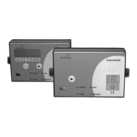
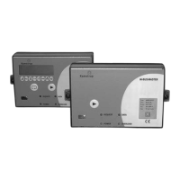
Describes two versions, components, front plate LEDs (Power, Overload, Request, Data), and its function as an RS232/optical repeater.
Explains the slave's role, installation in MULTICAL®, automatic data collection every 12 hours, and initiation process.
Describes the slave module for Compact/401, its intelligence, versions, and pulse input usage with MULTICAL® 401.
Details the slave for electricity meters, its pulse input, dimensions, and auto-detection of meter type.
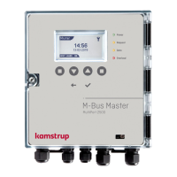
Explains how the module expands M-Bus network capacity and cable length, and its connection to M-Bus Masters.
Describes reading up to 40 meters via modem, mounting options, and reading software like PcModem.
Explains the parallel bus topology, starting from the master and connecting slaves sequentially, with error detection.
Shows wiring details for 230 VAC supply, M-Bus terminals (24/25), and serial data output on the M-Bus Master.
Explains how data is read using a PC program via IR-head or data cable connected to the M-Bus Master.
Introduces commands between M-Bus Master and Slave, and Slave to Master, relevant for heat meters.
Details commands like REQ_UD2, SND_NKE, and SND_UD1, including their function and format.
Outlines the step-by-step process for initializing the M-Bus network from master to slave.
| Input Voltage | 230 VAC |
|---|---|
| Short-circuit Protection | Yes |
| Overload Protection | Yes |
| Protection Class | IP20 |
| M-Bus Voltage | 36 V DC |
| Frequency | 50 Hz |
| Storage Temperature | -20-70°C |
| Dimensions | 90 x 70 x 60 mm |