8
Service and Repair Manual
Model 1400KV/1400BV
Fig. 4
Fig. 5
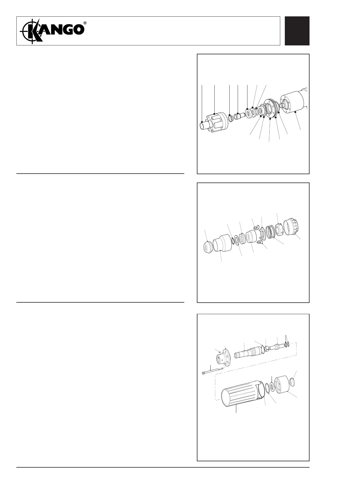
Fig. 6
Dismantling
the anvil
assembly
(1400, 1400B)
1. Remove the catcher housing (19) rubber ring (18)
and recoil absorber (17) from the anvil housing
(14).
2. Remove the anvil (13) and seal (12), recoil ring
(16) from the anvil housing (14).
3. Remove the locating ring (21), 'O' rings (22) &
(20) from the hammer casing (34).
4. Remove 'O' ring (20), from the anvil housing.
5. Place unit on a suitable protected surface and
remove liner (15) using Service Tool
9170 3022 90.
19
20
13 16
17
18121415
21
22
20
34
Dismantling
the SDS
assembly
(1400M)
1. Remove end cap (102) and chuck cover (103).
2. Remove the following items:
- wire clip (104)
- buffer stop (105)
- buffer (106)
- SDS chuck (107)
3. Remove two latches (108) and remove the
following items:
- latch plate (109)
- spring (110)
- lock plate (111)
- lock chuck (112)
Removing
the driver
(1400M)
1. Remove six screws (113), nose piece (115) four
balls (114) and trans housing (124).
2. Remove nose cover (120) and ‘O’ ring (121).
3. Remove the following items:
- driver (117)
- ‘O’ ring (126)
- junk ring (118)
- anvil (119)
- seal (12)
- ‘O’ ring (122)
- junk ring (123)
- recoil transfer ring (125)
102
104
106
108
109
111
103
105
107
108
110
112
113
114
115
117
118
126
119
12
123
125
124
122
121
120
 Loading...