19
Service and Repair Manual
Model 710/760
Service and Repair Manual
Model 760KV/SV/MV
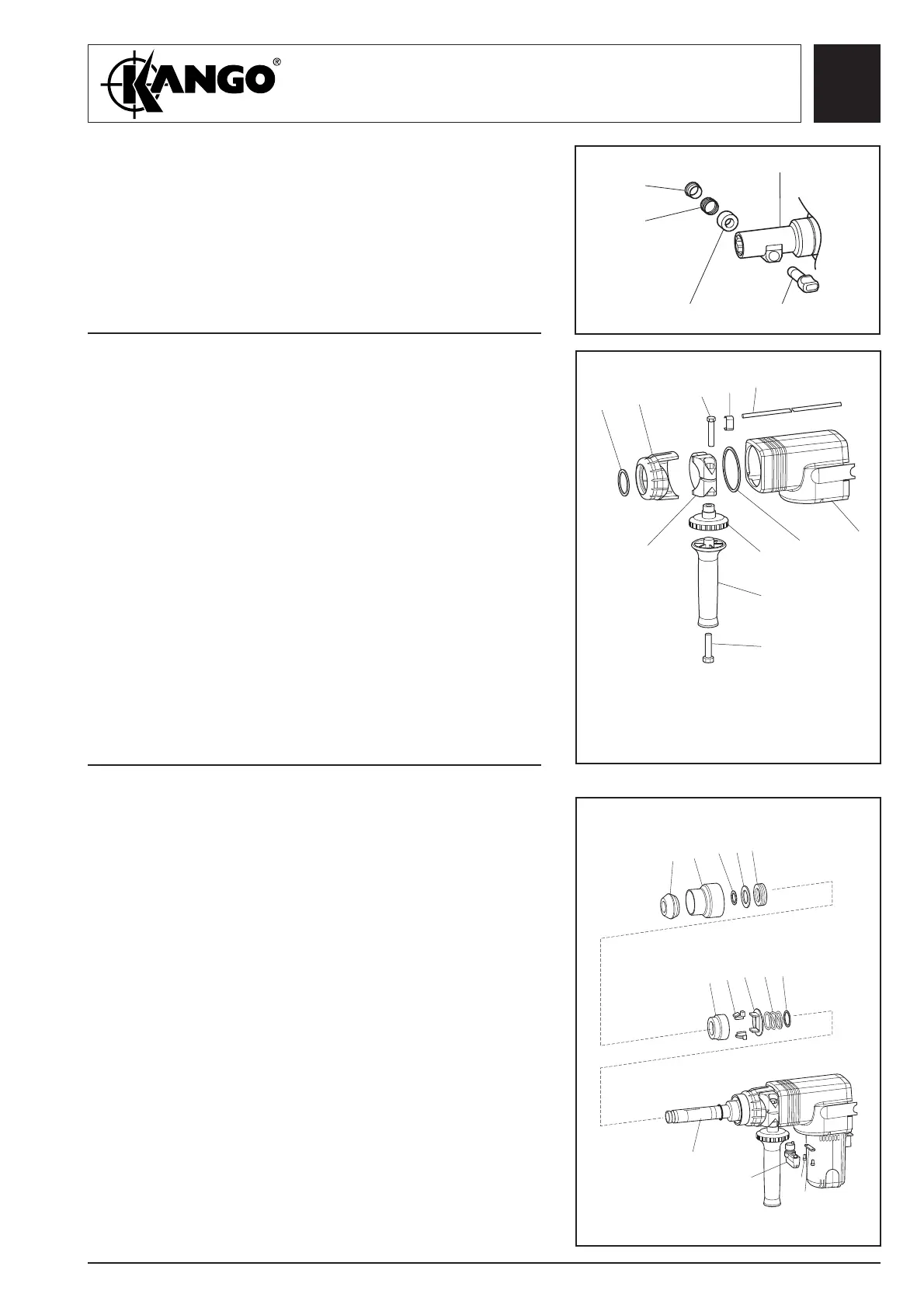
Fig. 28
Dismantling
the top cover
(KV, SV only)
1. Remove retaining ring (120) and pull off cover
(119).
2. Unscrew handle (116) and remove screw (117).
3. Remove clamping wheel (115), and withdraw
depth gauge rod (110), gauge clamp (111) and
screw (113).
4. Pull off strap casting assembly (114), remove top
cover retaining ring (118) and top cover (112).
117
116
115
118
112
114
120
119
113
111
110
Fig. 29
Dismantling
the switch
assembly
(MV only)
1. Remove two screws (147) and clamp plate (146).
2. Remove knob (145).
3. Remove nose cone end cap (139) and chuck cover
(138).
4. Remove the following items from driver (110):
- wire clip (137)
- buffer stop (136)
- buffer (135)
- chuck (134)
- latches (133)
- latch plate (132)
- latch spring (131)
- washer (130)
Dismantling
the latch bar
(KV, SV only)
1. Remove latch retainer (108), latch spring (107),
spring cover (106) and latch bar (105) from nose
piece (104).
Fig. 27
104
108
107
106
105
110
139
146
138
137
136
135
134
133
132
131
130
147
145
 Loading...