Do you have a question about the Kärcher HD 6/15 M and is the answer not in the manual?
Defines hazard levels (DANGER, WARNING, CAUTION, ATTENTION) and their meanings.
Explains the manual's structure: function groups, numerical legend, and textual display.
Specifies the approved applications and usage of the high-pressure cleaner.
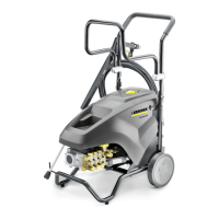
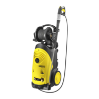
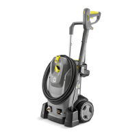
Lists the specific Kärcher high-pressure cleaner models covered by this manual.
Details the safety devices integrated into the unit to protect the user.
Describes the function of the overflow valve and its interaction with the pressure switch.
Explains the operation of the safety valve for overpressure protection.
Information about the device's type plate and its key identifiers.
Diagram and labeling of the electrical box for HD 6/15 MX.
Diagram and labeling of the pump head for HD 6/15 MX.
Detailed cross-section of the cylinder head for HD 6/15 M/MX.
Cross-section and function of the startup valve.
Cross-section and function of the pressure switch.
Cross-section and function of the overflow valve.
Diagram of the HD 6/15 M/MX pump set with labeled parts.
Cross-section of the motor showing its internal components.
Detailed cross-section of the cylinder head for HD 8/18 M.
Diagram and explanation of the overflow valve operation.
Diagram and explanation of the pressure switch operation.
Diagram and explanation of the pressure relief valve.
Diagram of the HD 8/18 M pump set with labeled parts.
Cross-section of the HD 8/18 M motor with labeled components.
Diagram of the HD 7/17 M pump set with labeled parts.
General safety instructions for performing service on the unit.
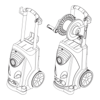
Overview of the unit's structure, referencing components and service activities.
Procedure for accessing the unit by opening and closing the cover.
Procedure for accessing the electrical components by opening/closing the box.
Steps to remove and install the electrical box for HD 6/15 MX.
Procedure for removing and installing the main chassis of the unit.
Instructions for removing and installing the hose reel angle piece.
Procedure for handling the shoulder module: removal, installation, disassembly.
Procedure for removing and installing a wheel on the unit.
Procedure for removing and installing the power switch linkage.
Steps for cleaning the water filter of the unit.
Information on diagnosing faults within this service group.
Critical safety guidelines for working with the electrical system.
Overview of the electrical system components and related service activities.
Procedure for removing and installing the capacitor.
Procedure for removing and installing the motor circuit breaker.
Procedure for removing and installing the power supply cable.
Procedure for removing and installing the power switch.
Procedure for removing and installing the contactor on HD 8/18 M.
Procedure for removing and installing the motor for HD 6/15 MX.
Procedure for removing and installing the motor for HD 8/18 M.
Service and inspection points for the electrical system.
Essential safety precautions for pump servicing.
Overview of pump components for HD 6/15 MX and HD 8/18 M.
Procedure for removing and installing the pipeline on HD 6/15 MX.
Procedure for removing and installing the pump head.
Steps for removing and installing high pressure seals.
Procedure for removing and installing suction valves on HD 6/15 MX.
Procedure for removing and installing suction valves on HD 8/18 M.
Procedure for removing and installing pressure retention valves on HD 6/15 MX.
Procedure for removing and installing pressure retention valves on HD 8/18 M.
Procedure for removing and installing pressure valves on HD 6/15 MX.
Procedure for removing and installing the pressure switch.
Procedure for removing and installing the startup valve on HD 6/15 MX.
Procedure for removing and installing the pressure relief valve on HD 8/18 M.
Procedure for removing and installing low pressure seals.
Procedure for removing and installing the non-cage pump set.
Procedure for removing and installing the cage pump set.
Procedure for removing and installing pistons and oil seals.
Procedure for removing and installing the swash plate for 2-pole motors.
Procedure for removing and installing the swash plate for 4-pole motors.
Procedure for removing and installing bearings and radial shaft seal.
Procedure for removing and installing the overflow valve.
Steps for draining and replacing the pump oil.
Troubleshooting steps for when the device fails to start.
Troubleshooting steps for insufficient pressure.
Comprehensive technical specifications and data for all listed models.
Circuit diagram for single-phase HD-M units.
Circuit diagram for single-phase HD-M units with contactor.
Circuit diagram for three-phase HD-M 380V-480V units.
Circuit diagram for three-phase HD-M 200V-240V units.
| Form factor | Compact |
|---|---|
| Hose length | 10 m |
| Power source | Electric |
| Castor wheels | Yes |
| Product color | Gray |
| Detergent tank | No |
| Pressure range | High-pressure |
| Maximum pressure | 225 bar |
| Maximum flow rate | 560 l/h |
| Working pressure (max) | 150 bar |
| Maximum water temperature | 60 °C |
| AC input voltage | 230 V |
| Number of phases | 1 |
| AC input frequency | 50 Hz |
| Power consumption (typical) | 3100 W |
| Package weight | 32000 kg |
| Depth | 400 mm |
|---|---|
| Width | 455 mm |
| Height | 700 mm |
| Weight | 28600 g |