© Copyright 2021 KE2 Therm Solutions, Inc., Washington, Missouri 63090
Q.1.64 October 2021
Page 2
KE2 EvaporatorEciency
Condensed Quick Start Guide
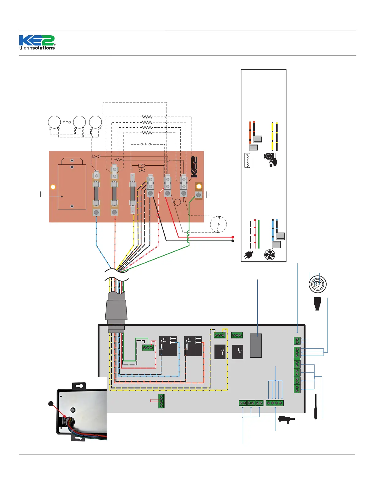
BL/BK
OR/BK
Y/BK
FAN/S
HEATERS
LL SOLENOID/COMP RELAY
BK/OR
L1
WT/R
L2
HS
GND
P/N 20996
12 AMP
20 AMP
3 AMP
OR NEUTRAL
HEATERS
thermsolutions
®
NO NC
COM
NO NC
COM
COM
NC
NO
COM
NC
N0
Solenoid Relay
Defrost
Relay
Fan
Relay
208-240
Power Input
Voltage Jumper
208-240 Default
L1
Ground
L2
COM
NC
NO
COM
NC
N0
Auxiliary Relay
Yellow with black stripe 16 AWG
Black with yellow stripe (L1) 16 AWG
Blue with black stripe 14 AWG
Black with blue stripe (L1) 14 AWG
LLS/Compressor
Fans
Black with white (L1) 16 AWG
White with red (L2/neutral) 16 AWG
Green (Ground) 16 AWG
Power
Orange with black stripe 12 AWG
Black with Orange stripe (L1) 12 AWG
Defrost Heaters
Supply Voltage
FAN
MOTOR
FAN
MOTOR
FAN
MOTOR
EVAPORATOR
FANS
HEATER LIMIT SWITCH
DEFROST HEATERS
LIQUID LINE SOLENOID
N.C.
R/W
BL/BK
BK
BL/BK
FROM
CONTROLLER
EC MOTOR
RELAY
See Q.1.30 Figure 3 for wiring
of the EC Motor Relay.
DI 1
DI 3
DI 2
door switch
system o
dual temp setting
external alarm
light switch
defrost interlock
defrost lockout
Digital Inputs
KE2 RSV
blue
orange
yellow
red
black
RJ45 Ethernet Connection
Temperature Sensors
Pressure
Transducer
T1SuctT4Aux T2AirT3Coil
green
red
black
Temperature Sensors (4)
Pressure Transducer
ground
signal
+5
Pressure Transducer
Wiring Detail
black
red
green
0-10V analog out for variable speed fans
+
_
Part Number 20222
Beacon replacement
controller required for
Beacon® I & II valves.
EEV Input
Liq. Line Solenoid Relay
LLS/Compressor Contactor
Wiring Schematic - Controller New Installation
For step-by-step wiring instructions see Q.1.3 KE2 Evap Quickstart Guide
Wiring Schematic - Controller New Installation
Q
Use Split Bushing ("Q" in the kit) to
prevent chang of the high volt-
age wires if routing through the
high voltage shield
 Loading...