© Copyright 2021 KE2 Therm Solutions, Inc., Washington, Missouri 63090
Q.1.64 October 2021
Page 3
KE2 EvaporatorEciency
Condensed Quick Start Guide
Diagnostic Test
After Intro Mode the KE2 Evap will scroll START DIAGNOSTIC TEST. The optional
Diagnostic Test helps conrm wiring is correct. Check that all system components
are o, then press and hold
ENTER
to start, or press
BACK
to skip the test.
In Diagnostic Mode the KE2 Evap will energize and de-energize each relay one at
a time to allow you to conrm that only the correct component is running. The
order is FAN RELAY, DEFROST RELAY (except air defrost), AUX RELAY, LLS RELAY.
When prompted by the display, conrm whether the relevant component is ON or
OFF. Press
ENTER
to proceed to the next step, or wait 2 minutes for the controller
to proceed to the next step automatically. During the LLS RELAY test, the EEV will
control to superheat and fans will turn on after 1 minute to prevent oodback.
Adjusting Controller Parameters
The Controller Navigation illustration on pg. 4 shows the controller menu struc-
ture. The default display of the controller shows actual room temperature, defrost,
or any alarm condition. Press
or
to move from the default display to the
next menu column. The VARIABLES menu column consists of the current sensor
readings, and the relay states. The MANUAL menu column allows manual control
of the EEV, relays, and contains network setpoints. The SETPOINTS menu column
contains all refrigeration and remaining setpoints.
The controller will display LOGIN when the user attempts to access the
SETPOINTS or MANUAL menu. The User Password (1111) provides access to the
ROOM TEMP setpoint. Access to the full SETPOINTS or MANUAL menu requires
the Installer Password (2222).
Press
BACK
at any time to return to the next level up in the menu. A second/third
press will return to the default display.
Controller Setup: Intro Mode
The controller enters Intro Mode the rst time power is applied, which consists
of as little as 4 setpoints that must be congured to begin controlling the system.
Step ❶ - The rst setpoint to enter is ROOM TEMP. The default is 0.0
º
F, and the
right most 0 will be ashing. Use
and
to change the digit being modied.
Press
to raise the temp, and
to lower the temp. Once you have the desired
room temp, press and hold
ENTER
for three seconds.
Step ❷ - Next, DEFROST TYPE then ELEC (electric) will be displayed. The con-
troller is designed to work with electric, hot gas, and air defrost. Press
or
to
select the correct defrost type, then press and hold
ENTER
for three seconds.
Step ❸ - VALVE TYPE then MECHANICAL will be displayed. If the expansion
valve is mechanical (TEV), press and hold
ENTER
for three seconds. If you have
an electric expansion valve (EEV), use
or
to navigate to the correct valve
model. With the correct EEV displayed, press and hold
ENTER
for three seconds.
NOTE: If an EEV is selected, you will be prompted to specify the REFRIGERANT.
The KE2 Evap may also be applied with user-dened CUSTOM EEVs. When CUS-
TOM is selected, the user is also prompted to select MOTOR TYPE, MOTOR STEP
RATE, and MAX VALVE STEPS.
Step ❹ - The fourth prompt is whether KE2 SMART ACCESS is ENABLED or
DISABLED. KE2 SMART ACCESS allows you to view your controller online. Make
your selection by using
or
then press and hold
ENTER
for three seconds.
These are the only setpoints required to begin controlling the system. For setup
with multi-evaporator applications see bulletins Q.5.10 and Q.1.32
Install the air temp sensor using the air sensor mount
K
, approximately 2/3 down from the top
of the evaporator, and 8 - 12 inches from coil in the return air of the evaporator.
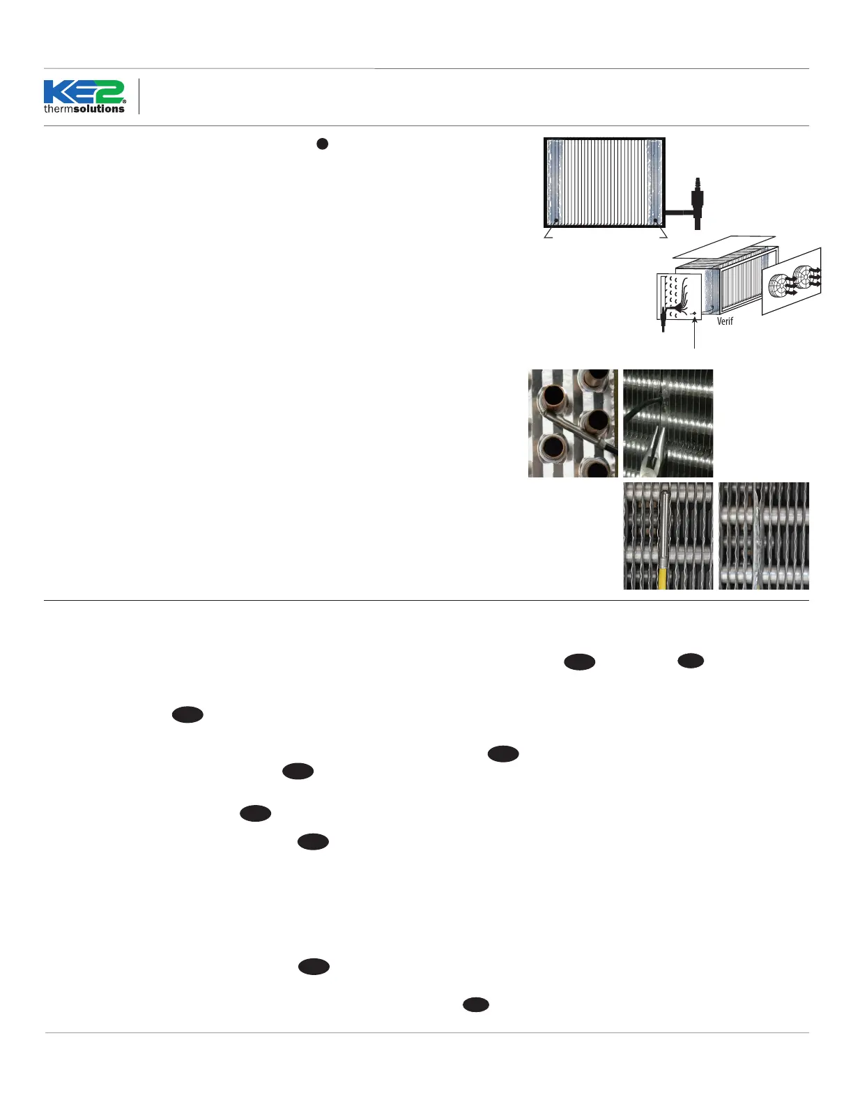
IMPORTANT: Determine the coil sensor location
When arriving on site, put the system into defrost and observe where frost is last to disap-
pear on the coil. Place one sensor in each of the last two places where frost disappears ❶.
Monitor the evaporator’s air entering and exiting sides. Often the last place frost disappears is
on the air exiting side, near the right or left end. Verify all heating elements are working properly.
Sensor location is often approximately 1 to 1-1/2” away from the right and left edges of the ac-
tive coil surface, near the top or bottom 1/3rd of the evaporator, as far away from the defrost
heat sources as possible. Ice tends to grow from the edges inward, but verify coil sensor loca-
tions by observing an actual defrost. Do not install coil sensor on the U-bends.
Note: To prevent sensor wire damage from sharp edges, insert plug I into coil housing - ❷.
Plug is inserted in the inner housing to access the coil. Puncture plug to insert sensor wire.
The sensor should touch two circuit tubes ❸. When inserting the sensor into the coil, the tip
should touch one of the circuit tubes. Don’t locate it next to the heating elements. In ❹ the
probe is inserted into the ns approximately 1/16” deeper than the stainless shielding. Pinch
the ns gently together, securing the sensor. This also provides thermal ballast, ensuring a com-
plete defrost.
Alternate method - As the defrost termination sensor, it is critical the sensor does not termi-
nate defrost before all frost is removed from the coil. In some installations, inserting the sensor
into the coil may position it too close to the defrost heat source. An alternate method of po-
sitioning places the sensor vertically between the coil ns, see ❺. Pinch ns together gently,
securing the sensor.
Extending sensor wires
After the sensors are mounted, route them back to the controller. If the wires must be ex-
tended, use 18 gauge twisted shielded pairs. Max recommended length for 18 gauge: 100ft.
When running the wires back to the controller, do not induce noise on the sensor wires. This
occurs when sensor wires are located near high voltage lines (dened by UL as greater than
30V). Do not run high voltage and low voltage wires in the same conduit.
If crossing a high voltage line, run the sensor wiring at right angles to minimize noise.
Verify where frost is last to
disappear by initiating a defrost,
and observing last spots to clear.
Verify where frost is
last to disappear
(often on air exiting side).
Item I from Parts List on page 1
❶
❷
❺
❹❸
 Loading...