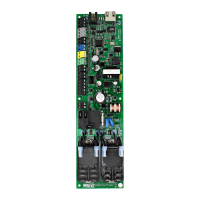
EasyManua.ls Logo

KE2 EvapOEM - User Manual

KE2 EvapOEM
21 pages
Print Icon
To Next Page IconTo Next Page
Loading...
KE2 EvapOEM
Quick Start Guide
PN 21231 (21214v3.0)
Q.1.45 October 2022
thermsolutions
© Copyright 2022 KE2 Therm Solutions, Inc., Washington, Missouri 63090
This reference should remain on site with
the installed KE2 Evap OEM controller.
Overview
The KE2 Evap OEM provides the energy savings, precise temperature control,
frost reduction, and communications capability of the KE2 Evaporator Eciency
in a compact and economical package. It replaces and performs the function
of multiple mechanical components such as the thermostat, defrost time clock,
defrost termination, and fan delay. The KE2 Evap OEM controls the liquid line
solenoid (LLS), evaporator fans, and defrost heaters (if present). It is able to
control an electronic expansion valve (EEV) to regulate superheat, but will also
function with a mechanical thermostatic expansion valve.
Defrosts are initiated by a proprietary calculation of actual evaporator
eciency. When evaporator eciency has dropped to 90%, the controller will
initiate a defrost. Defrost is terminated based on one or more coil temperature
sensors. To maximize eciency, fans may run for several minutes at the start of
a defrost before turning o and energizing heaters.
Fans are also managed in a unique way. If wired to control fans with fan
management enabled, during the o cycle the controller will intelligently cycle
fans based on room and coil temperature for precise room temperature control.
Fans should always be running when the controller is calling for refrigeration.
Communications capability on the KE2 Evap OEM was designed with the
service technician in mind. The controller has built-in webpages that show
system performance in real time, allow setpoint changes, provide a 30 day
room/coil temperature graph, and a 30 day datalog of all variables. The
webpages can be accessed by smartphone or tablet through a KE2 Therm Wi-
Fi accessory, a local network, or by plugging directly into the controller with a
Cat5e cable and laptop. If the controller is provided wired internet access, it can
be accessed remotely via KE2 SmartAccess.
NO NC
COM
EARTH
ON
Panic
Alarm
Light
Control
Temp
Alarm
Door Heater
Control
Remote
Display
+
Liquid Line Sol./
Comp. Contactor
Defrost Heater
Management
Precise Room
Temperature
TEV/EEV
Multiple
Alarms
Evap. Fan
Management
Remote Access
& Control
Data
Logging
KE2 Combo Display
KE2 Evap OEM
+
Humidity Control
& Monitoring
Heat / Reheat
Timer
Output
Humidier /
Dehumidier
Superheat Control
Based on Humidity
KE2 Humidity Control
SHSHSH
Contents
Point to Point Wiring Diagram
Controller with KE2 Terminal Board Page 2
General Wiring Diagram
Controller without KE2 Terminal Board Page 3
Coil Sensor Location Page 4
Navigation / User Interface / Setup Page 5
Key Presses / Bonding / Pairing Page 6
Menus and Parameters
Basic Setpoints Menu Page 7
Advanced Setpoints Menu Page 7-9
Alarm Status Menu Page 10
Variables Menu Page 11
Types of Control - First Time Setup Menu Page 12
System Modes Page 12
Auxiliary Input Modes Page 12
Valve Types Page 12
Refrigerants Page 12
Alphabetical List of Abbreviations Page 13-17
KE2 SmartAccess Page 18
Dimensions Page 19
Accessories Page 20
Specications Page 21
Get your controller
online, & benet from remote
monitoring, control, and text /
e-mail alarm notices.
Just a few easy steps, with
KE2 SmartAccess
FIRST YEAR FREE
NO COM MIT MEN T R EQU I RED
This Quickstart guide provides an overview of the controller, general wiring,
basic display operation, and setpoints. Please follow the link below for the
latest version of this document, alarm troubleshooting guide, and webpage
explanations for further information.
KE2 Evap OEM Literature
https://ke2therm.com/literature/literature-ke2-evap-oem/
KE2 Combo Display
KE2 Evap OEM controllers may be installed with the KE2 Combo Display. The KE2
Combo Display provides a remote display for the KE2 Evap OEM and a number
of extra features. Please follow the link below for further information on the KE2
Combo Display.
KE2 Combo Display Literature
https://ke2therm.com/literature/literature-ke2-combo-display/
KE2 Humidity Control
KE2 Evap OEM controllers with rmware v3.0 or above may add the KE2
Humidity Control to new or existing installs. This adds humidity monitoring
& control, including outputs for humidication, dehumidication, heat, and a
unique superheat control designed to maximize or minimize dehumidication.

Other manuals for KE2 EvapOEM

Questions and Answers

Summary

Overview of KE2 EvapOEM Controller

Energy Savings and Control Capabilities

Describes energy savings, temp control, frost reduction, and component replacement.

Defrost Initiation and Termination

Explains defrost initiation based on efficiency and termination based on sensors.

Fan Management

Details how fans are managed during cycles and defrosts for precise control.

Communications Capability

Highlights built-in webpages for real-time data and remote access.

Point-to-Point Wiring Diagram with Terminal Board

General Wiring Diagram without Terminal Board

Coil Sensor Installation and Location

Sensor Installation

Describes how to position the sensor for optimal defrost termination.

Alternate Positioning Method

Explains placing the sensor vertically between coil fins for specific scenarios.

Extending Sensor Wires

Provides guidance on extending sensor wires and avoiding electrical noise.

Technical Videos for Sensor Installation

Links to YouTube videos for coil sensor placement and installation guidance.

KE2 Basic Display Navigation and Setup

Navigation Using the Basic Display

Instructions on how to navigate menus and change setpoints on the basic display.

Controller Setup - Introduction Mode

Guide for the initial setup process, including Types of Control, Refrigerant, and SmartAccess.

Variables Menu

Explains how to view real-time system information using the Variables Menu.

Changing Setpoints

Details on accessing and modifying basic and advanced setpoints.

Manual Valve Control

Instructions for manual operation of the EEV valve.

Manual Defrost

How to initiate and manage manual defrost cycles.

System Operation Modes and Lockout

System Off (Pumpdown)

How to place the controller in system off mode and exit.

Display Lock

Method to lock the display to prevent unintended changes.

Diagnostics Mode

Procedure to run diagnostics by energizing relays for 30 seconds.

Web Interface and Security Features

Web Login

Information on default credentials and changing passwords.

Resetting the Controller Web Password

Steps to reset forgotten web login credentials.

Controller Bonding and Pairing Procedures

Bonding (Multi-Evap Applications)

Synchronizing multiple controllers for refrigeration and/or defrost.

Pairing (Lead;Lag, KE2 Combo Display)

Setting up two controllers for lead/lag or display on a single KE2 Combo Display.

Menus and Parameters Overview

BASIC Setpoints Menu

Lists basic setpoints accessible via the Basic Display or KE2 Combo Display.

ADVANCED Setpoints Menu

Details advanced setpoints, their ranges, defaults, and descriptions.

Setpoint Descriptions

Explanation of various setpoints including temperature, defrost, and fan settings.

Advanced Setpoints Menu Details

Auxiliary Input Settings

Configuration options for auxiliary inputs (state, mode).

Humidity Control Setpoints

Parameters related to humidity control, setpoints, and alarms.

Superheat and Dehumidify Settings

Details on superheat targets and dehumidify temperature offsets.

Alarm and Diagnostics Settings

Configuration for alarms, clear alarms, and diagnostics mode.

Network and Pairing Settings

Settings for web password reset, pairing, and bonding.

Advanced Setpoints for Valve, Fan, and Environment Control

Motor and Valve Control Parameters

Settings for motor type, step rate, and valve steps.

Fan and Defrost Timing Parameters

Includes fan delay, defrost delay, and pump down time settings.

Multi-Evap Control and Sensor Settings

Parameters for multi-evaporator control and sensor management.

Offset Settings for Sensors and Humidity

Offsets for various sensors and humidity targets.

Timer Settings for Humidity Control

Configuration for timer start/stop times for humidity control.

Alarm Status Menu and Descriptions

General Alarm Status

Describes common alarm abbreviations and their meanings.

Sensor and Communication Alarms

Details alarms related to sensors, communication errors, and external inputs.

Pressure and Defrost Alarms

Explains alarms related to low pressure, compressor cycles, and defrost timing.

Door and Temperature Alarms

Covers alarms for door status, high/low temperatures, and monitor temps.

Humidity Alarms

Describes humidity related alarms and communication status.

Variables Menu for Real-time Data

Temperature and Humidity Variables

Lists variables for room temp, humidity, coil temp, and superheat.

System Status and Relay Variables

Details system mode, relay status, and input status.

IP Address and Firmware Information

Variables related to controller IP address and firmware version.

Initial Setup: Types of Control and SmartAccess

Types of Control

Defines electric/air defrost and mechanical/EEV valve configurations.

KE2 SmartAccess Mode

Enables or disables KE2 SmartAccess for remote monitoring.

Auxiliary Input Modes Configuration

Input Mode Descriptions

Explains how auxiliary inputs can be configured for various functions.

Valve Type Selection

Valve Type Definitions

Lists and describes available valve types like Mechanical, Pulse, and KE2 RSV.

Refrigerant Type Selection

Refrigerant Information

Lists common refrigerants supported by the controller.

System Mode Indicators

System Mode Descriptions

Explains various system operating modes like Evap, Refrigerate, and System Off.

Alphabetical List of Abbreviations (A-C)

Alphabetical List of Abbreviations (D-E)

Alphabetical List of Abbreviations (E-H)

Alphabetical List of Abbreviations (L-P)

Alphabetical List of Abbreviations (R-U)

Introduction to KE2 SmartAccess

KE2 SmartAccess Online Access

Steps to enable and access KE2 SmartAccess via a web portal.

Preliminary Setup Options

Connecting the controller and options for network management.

KE2 SmartAccess Setup with KE2-EM

Guidance on setting up SmartAccess with the KE2-Edge Manager Plus.

KE2 Basic Display Dimensions

Controller Accessories and Parts

Panel Kits

List of available panel kits for controller mounting and integration.

Displays

Details on available display units for the controller.

Auxiliary Boards

Options for adding auxiliary control and monitoring boards.

Sensors

List of available temperature and humidity sensors.

Communications

Accessories for network connectivity like switches and managers.

Pressure Transducer

Available pressure transducers and their specifications.

RSV - Refrigeration Stepper Valves

List of refrigeration stepper valves and their connections.

External Relays

Relays for alarm outputs and mechanical relay options.

Replacement Relays and Fuses

Parts for replacing common relay and fuse components.

Controller and Component Specifications

Controller Specifications

Electrical, ambient, operating conditions, inputs, valve types, relays, and communication.

Pressure Transducer Specifications

Pressure range, proof pressure, burst pressure, and operating temperature.

Temperature Sensor Specifications

Details on the temperature sensor's operating range and packaging.

Technical Videos

Links to helpful video guides for troubleshooting and setup.

KE2 EvapOEM Specifications

General IconGeneral
BrandKE2
ModelEvapOEM
CategorySecurity System
LanguageEnglish