© Copyright 2022 KE2 Therm Solutions, Inc., Washington, Missouri 63090
Q.1.45 October 2022
Page 2
KE2 EvapOEM
Quick Start Guide
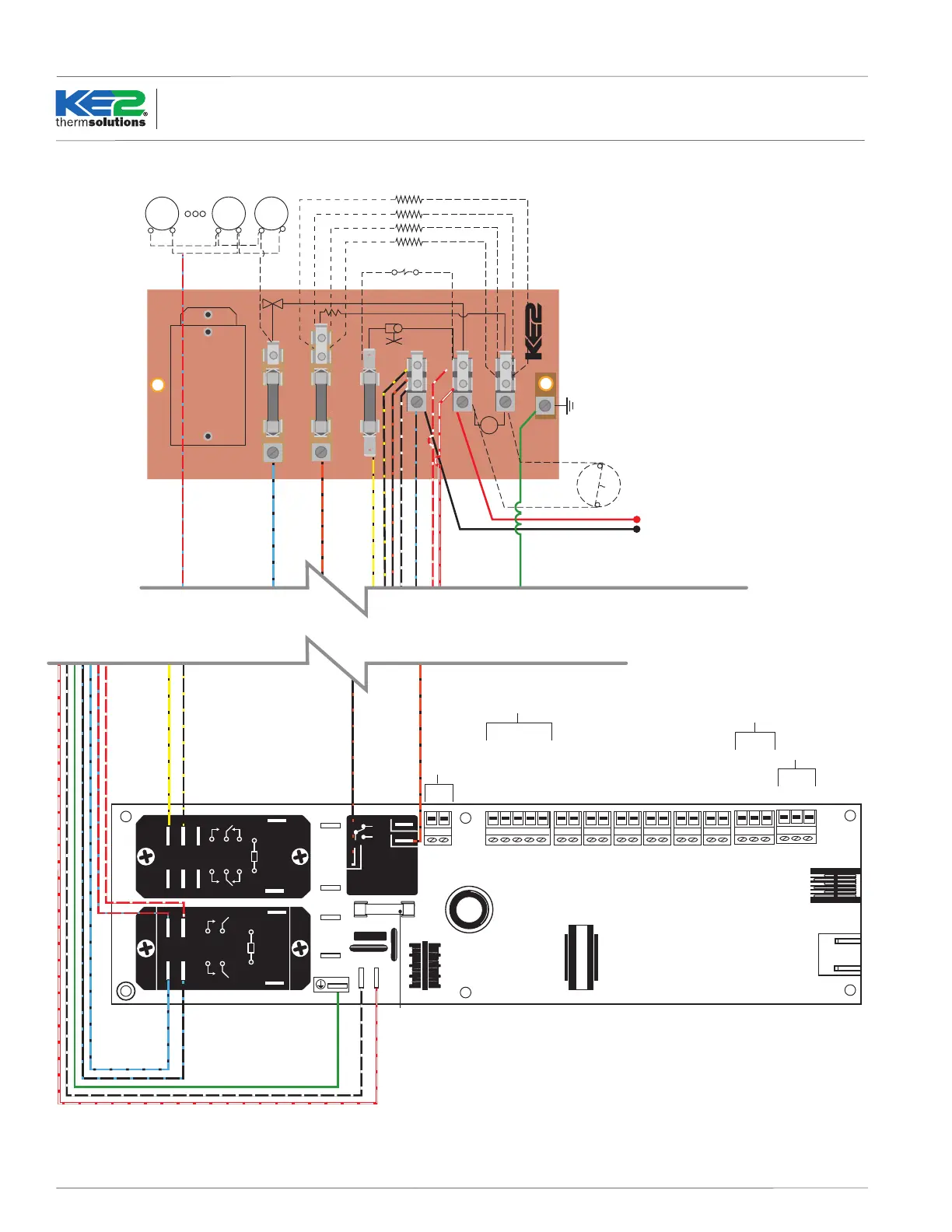
BL/BK
OR/BK
Y/BK
FAN/S
HEATERS
LL SOLENOID/COMP RELAY
BK/OR
L1
WT/R
L2
HS
GND
P/N 20996
12 AMP
20 AMP
3 AMP
OR NEUTRAL
HEATERS
thermsolutions
®
R/W
BL/BK
BK
BL/BK
FROM
CONTROLLER
EC MOTOR
RELAY
NO NC
COM
TSuc
Aux3
Aux2
Aux1
TCoil
TAir
0 to 10VDC Output
Alarm Relay**
Door Alarm Relay**
Variable Speed Fan
Ethernet Display
Defrost Relay
Liquid Line Solenoid/
Comp. Contactor Relay
Fan Relay
Blue
Orange
Yellow
Red
Black
Empty
Red
Green
White
Black
EEV
A
B
Shield
RS 485
Line/L1
Neutral/L2
Incoming Power
Red (+5 VDC)
Black (0 VDC)
Green (Signal)
Pressure Transducer
NO
COM
NC
NO
COM
Ground*
EARTH
Chassis
Ground*
Fuse
NO
COM (L2)
+
–
+
–
*Use only chassis ground or
spade connector ground.
**Requires PN 21304
Supply Voltage
Fan
Motor
Fan
Motor
Fan
Motor
Evaporator
Fans
Heater Safety/High Limit Switch
Defrost Heaters
Liquid Line Solenoid
N.C.
2 4
6
8
1
0
1
0
2 4
6
8
3
7
Point to Point Wiring Diagram - Controller with KE2 Terminal Board