Do you have a question about the KEB 2MF5280-2032 and is the answer not in the manual?
Information provided without responsibility, applies to user-specific advice and tests.
Operations require skilled personnel familiar with dangers and relevant standards.
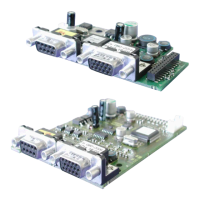
Document covers installation, connection, and setup for KEB interface cards with two interfaces.
Explains the coding of material numbers based on interface type and housing size.
Lists items included in the encoder interface package, such as manuals and fixing bolts.
Describes internal/external voltage supply for COMBIVERT and encoder interfaces, including current calculations.
Notes that Channel 2 description depends on the encoder interface and is in a separate manual.
Lists technical parameters for the X3A interface, including type, channels, and frequency.
Details the pinout and connection guidelines for the X3A SUB-D15 socket.
Covers process data signals, encoder signal descriptions, and breakage recognition logic.
Provides guidelines for encoder cable connection, shielding, and specifications.
Details maximum cable length calculation and lists tested EnDat encoder models.
Explains how EnDat parameters are stored and managed within the encoder.
Describes status messages and error codes displayed by parameter Ec.37 for encoder operation.
Explains how to interpret EnDat encoder errors and lists common bit-coded error messages.
Details the use of parameter Ec.38 for reading and writing encoder settings.
This document describes the COMBIVERT EnDat Encoder Interface, a component designed to integrate EnDat encoders with KEB inverters/servos, providing precise position and speed feedback for various industrial applications. The interface card supports two channels, with Channel 1 specifically configured for EnDat encoders.
The EnDat Encoder Interface facilitates synchronous serial communication with EnDat encoders, allowing for the acquisition of absolute position data without the need for a reference point search during start-up. It supports both incremental signals (A+, A-, B+, B-) for counter and direction detection, and serial data channels (Data+, Data-) for absolute position and other encoder information. The interface card is designed to be installed within the COMBIVERT inverter/servo, drawing its internal voltage supply from the main unit and providing regulated voltage outputs (24V and 5.25V) for encoder power.
A key feature is the continuous monitoring of encoder signals and communication. During start-up, and subsequently every 30 ms, the interface queries the encoder for its absolute position. The system tracks position differences and triggers an error (Ec.37=69) if the difference increases too rapidly or exceeds a maximum value, indicating a potential encoder breakage or malfunction. The incremental track is monitored approximately every 16 ms for signal level integrity, while the absolute track (serial communication) is continuously checked for responsiveness. If the encoder fails to respond or communication is not possible, a corresponding state message is transmitted to the inverter.
The interface also incorporates encoder breakage recognition, a software function that activates during encoder rotation. Initialization of this feature begins by writing to parameter Ec.0. After successful initialization, the correct position data is transmitted. The response time for encoder communication errors can vary, potentially exceeding 100 ms depending on the encoder type.
Channel 1 (X3A - EnDat Interface):
Voltage Supply:
Encoder Cable Specifications (KEB encoder cables):
Tested EnDat Encoders (examples):
Mechanical Installation: The interface card is installed by authorized personnel following EMC and safety rules. This involves de-energizing the inverter, waiting for capacitor discharge, removing the operator and plastic cover, fixing the interface board straightly from the socket connector, screwing in the fixing bolt, and reattaching the plastic cover.
Encoder Connection (SUB-D15): The encoder cable should be double-shielded and twisted in pairs. The exterior shielding must be connected to PE/GND at both ends, while interior shieldings are connected to COM at one side. It is crucial not to interconnect exterior and interior shielding. The document provides a detailed pinout for the SUB-D15 connector (Socket X3A) and the motor encoder plug, including signal names, pin numbers, and core colors for proper wiring.
Start-up and Parameter Adjustment: After installation, specific adjustments are required in the inverter/servo software. This includes switching on the inverter, selecting the application mode, and setting ud.2 to F5-S for synchronous motors. Key parameters to configure are:
EnDat Parameters: The EnDat encoder stores various parameters that are automatically or manually read/written via Ec.38. These include parameters for synchronous motors (dr.23...dr.28, dr.30...32), asynchronous motors (dr.0...dr.7), encoder parameters (Ec.1...3, In.31...32), and controller parameters (cS.19).
Encoder Status Monitoring (Ec.37): Parameter Ec.37 provides comprehensive status messages for the encoder and interface, aiding in troubleshooting.
Read/Write Encoder 1 (Ec.38): This parameter allows for reading and writing encoder parameters, which is crucial for configuration and maintenance.
The comprehensive error reporting and parameter management features ensure efficient diagnosis and resolution of issues, contributing to the reliable operation of the drive system.
| Brand | KEB |
|---|---|
| Model | 2MF5280-2032 |
| Category | Recording Equipment |
| Language | English |