KEETEC RIDER MANUAL
EN
VI. PROGRAMMING OF REMOTE CONTROLS
The system allows you to program up to 10 remote controls.
Activation of the remote control programming mode is possible during
the first minute after entering into service mode.
NOTE: By starting the pairing process and pairing of new drivers, the
existing paired remote controls will be automatically removed from the
system, therefore pair also the original remote controls again.
Remote control programming procedure:
• Enter the service mode (see chapter IV. - SERVICE MODE)
• Turn on the ignition and press the service button 5 times within one
minute.
• Entering the remote control pairing mode is announced by a long
beep of the buzzer and quick periodic flashing of the LED on the
service button.
• Press and hold the button on the remote control until the LED turns
off.
• Pair all the controllers you want to use one by one.
• To exit the pairing mode, turn off the ignition. The end of the mode
is signaled by 2 x long beeps of the buzzer.
Note: In case of unsuccessful programming new remote controls, the
original remote control remain in the device’s memory.
VII.
CHANGING BATTERY IN REMOTE CONTROL
A critical battery voltage level is signaled by the buzzer beeping 3 times
when the ignition is switched on or the engine is started.
Carefully open the remote control cover with a flat screwdriver. Remove
the dead battery and insert a new one, pay attention to the polarity of
the battery when replacing. Use CR2450 type only.
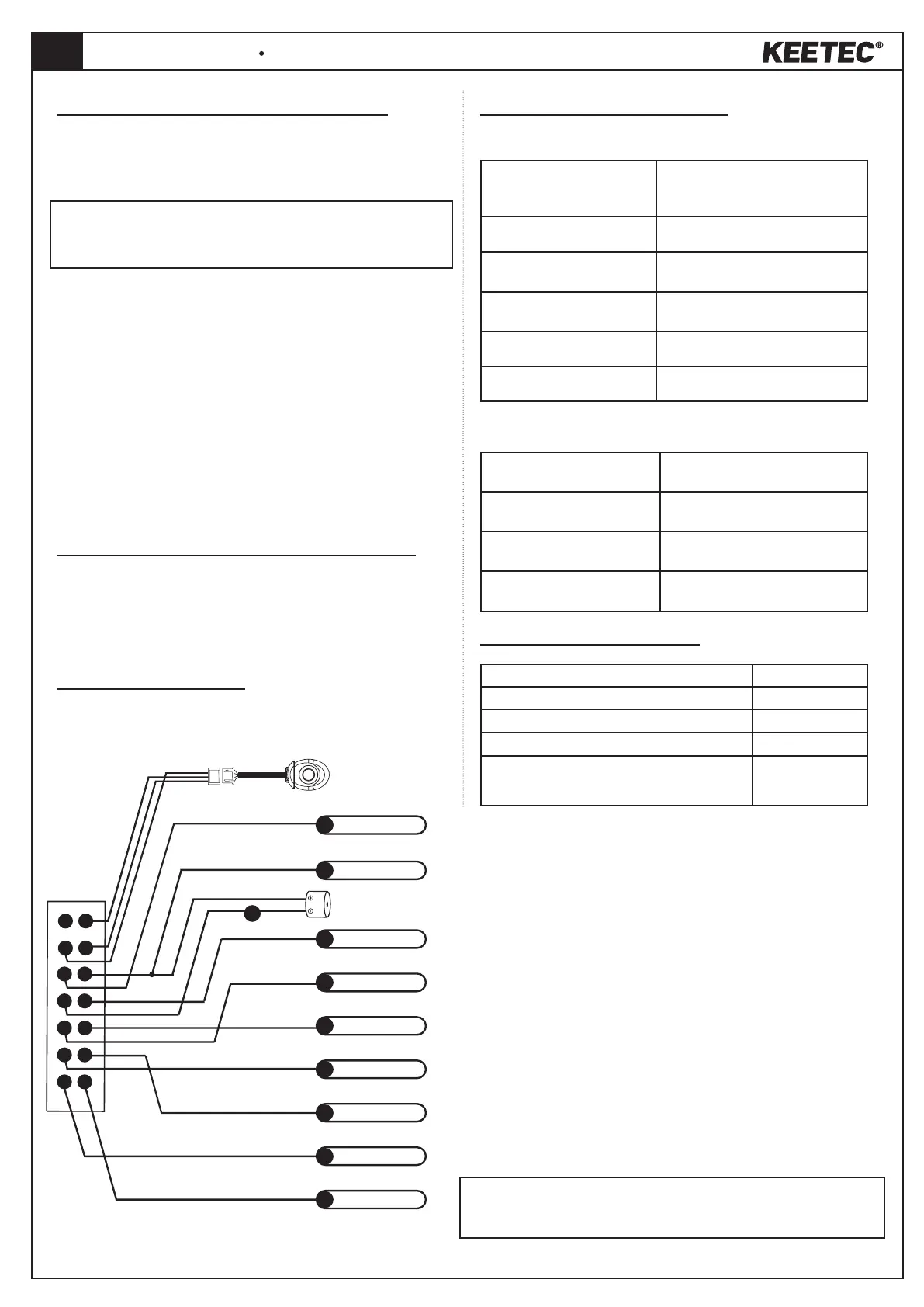
VIII. WIRING DIAGRAM
IX. SIGNALING OF THE SYSTEM
Acoustic signaling by buzzer
5x short beeps
Activation/deactivation of service
mode, ignition on when activated
service mode
4x short beeps
Remote control is out of reach
3x short beeps
Critical remote control battery
voltage level
2x short beeps
Confirms emergency deactivation
1x long beep
Enter remote control pairing mode
2x long beeps
Exit remote control pairing mode
Optical signaling of the LED service button
Constantly lit
Indication of service mode when
the ignition is on
Fast flashing
Indication of pairing mode of new
remote controls
3 flashes
Confirmation of digit entry PIN
code
1flash in 3 sec.
Remote control is not in the system
coverage area
X. TECHNICAL PARAMETERS
Voltage 12/24 V
Operating temperature of the device -40°C to +80°C
Consumption at idle 4,7 mA
Max current for immobilizer relay 1 A/24 V
Dimensions 14 x 20 x 67 mm
Service Button
5
Ground
6
Power (+12/ 24 V)
8
Ignition
9
NC 2
10
NC 1
11
COM 2
12
COM 1
13
NO 2
14
NO 1
Buzzer
7
MARKING OF WIRES
(5) Ground
(6) Power Supply (+12/24 V)
(7) Buzzer (-150mA)
(8) Ignition (+)
(9) NC 2 blocking relay contact
(10) NC 1 blocking relay contact
(11) COM 2 blocking relay contact
(12) COM 1 blocking relay contact
(13) NO 2 blocking relay contact
(14) NO 1 blocking relay contact
The immobilizer follows the NC blocking logic. With a valid authorization, the
contacts NC 1 are connected to COM 1 and NC 2 to COM 2.
Warning: Keep the maximum permissible current load of the blocking relay 1A!
To control a larger current load, use additional equipment!
 Loading...