SECTION2
Operation
2.5 IEEE-488 BUS CONNECTIONS
2.5.1
Bus
Connector
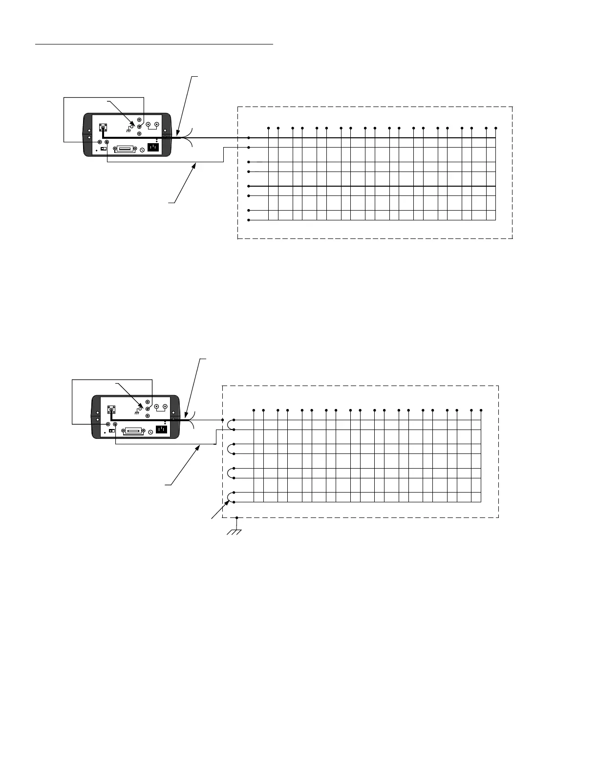
The Source Measure
Unit
can be connected to the
IEEE-488
bus through a cable equipped with standard
IEEE-488
connectors, an example of which
is
shown
in
Figure
2-16.
The connector can be stacked to allow a
number of parallel connections
at
one instrument. Two
screws are located
on
each connector to ensure that con-
nections remain secure. Current standards call for metric
threads, which are identified with dark colored screws.
Earlier versions
had
different screws, which were silver
colored. Do not attempt to use these types of connectors
on the Source Measure Unit,
which
is
designed for metric
threads.
©)
~·:::::::::::i~
©)
Figure
2-16.
IEEE-488
Connector
2.5.2
Multiple
Connections
A typical connecting scheme for a multi unit test system
is
shown in Figure
2-17.
Although
up
to
14
connectors
could theoretically be stacked
on
one instrument,
it
is
rec-
2-20
+
+
ommended that
you
stack no more
than
three connectors
on
any one unit to avoid possible mechanical damage.
2.5.3
Recommended
Cables
In
order to minimize interference caused
by
electromag-
netic radiation, it is recommended that only shielded
IEEE-488
cables be used. The Models
7007-1
and
7007-2
shielded
IEEE-488
cables are available from Keithley.
2.5.4
Connection
Procedure
Connect the
Source
Measure
Unit
to the
IEEE-488
bus as
follows:
1.
Line
up
the cable connector with the connector
lo-
cated
on
the rear panel of the
Source Measure
Unit.
The connector
is
designed so that
it
will fit only one
way.
2.
Tighten the screws securely,
but
do
not
overtighten
them.
3.
Add
additional connectors from other instruments,
as required.
4.
Make certain that the other end of the cable
is
prop-
erly connected to the controller. Most controllers are
equipped with
an
IEEE-488
style connector,
but
a
few may require a different type of connecting cable.
Consult the instruction manual for your controller
for the proper connecting method.
2.5.5
Bus
Limitations
The
IEEE-488
bus
is
limited to a maximum of
15
devices,
including the controller. The maximum cable length
is
20-meters,
or
two meters times the number of devices,
whichever
is
less. Failure to observe these limits may re-
sult
in
erratic bus operation.
 Loading...


