GUARD
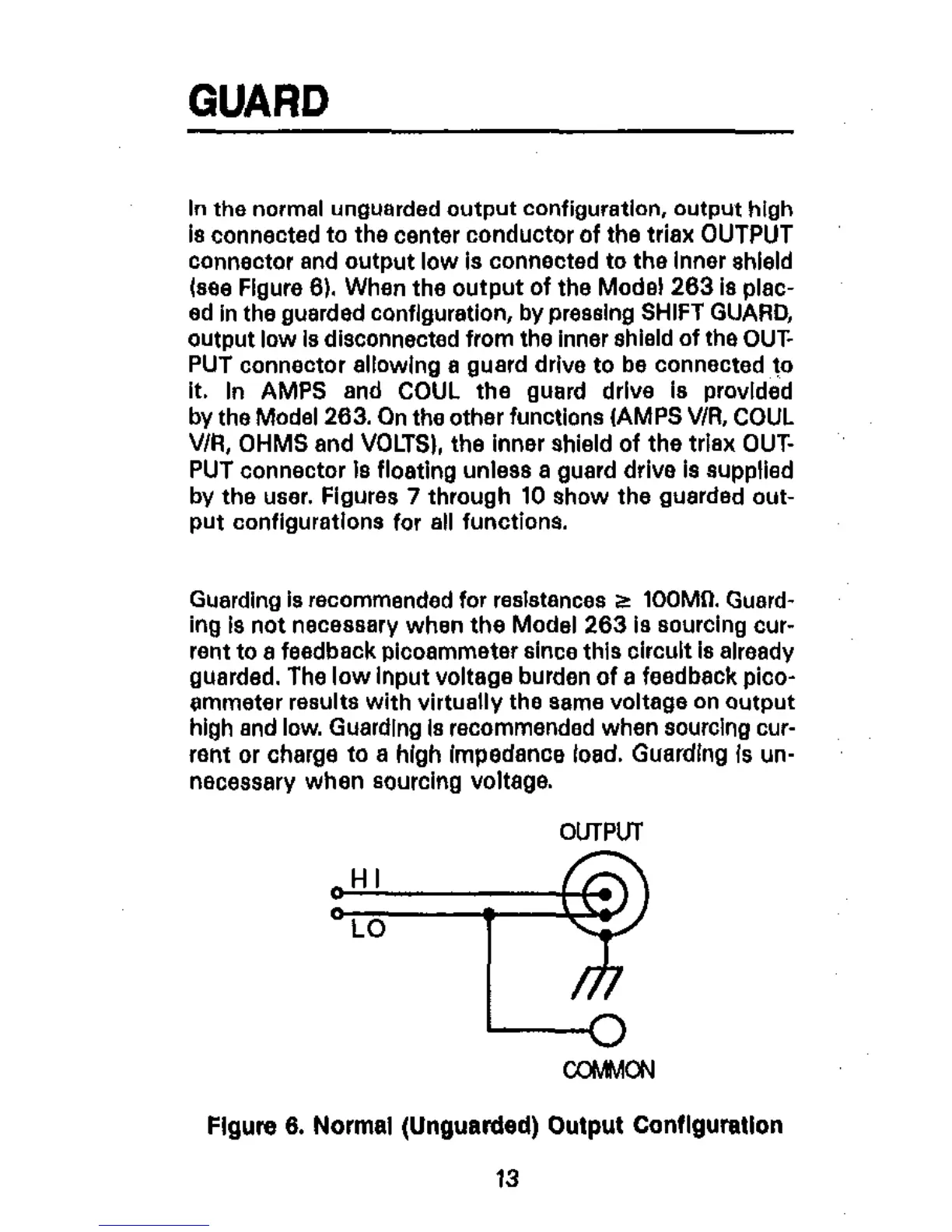
In the normal unguarded output con‘iguratlan, o”tp”t high
is connected to the center conductor of the triax OUTPUT
connector and outp,” low is connected to the Inner shield
Isee Figure 8). When the o”tput of the Mods1 203 18 plac-
ed I” the guarded conflguration, by pressing SHIFT GUARD,
output low Is disconnected from the inner shield of the OUT.
PUT connector ellowlng a guard drive to be connected to
it. In AMPS and COUL the guard drive is provided
by the Model 283. On the other functions (AMPS V/R, COUL
V/R, OHMS and VOLTS), the inner shield of the triax OUT-
PUT connector Is floating unles8 a guard drive is supplied
by the user. Figures 7 through 10 show the guarded out-
put configurations for all functions.
Guarding 18 recommended for r~slstancw8 2 100Mg. Gusrd-
ing is not necessary when the Model 263 is sourcing cur-
rent to a feedback picoammeter since this oircult is already
guarded. The low Input voltage burden of a feedback pico-
mmeter results with virtually the some voltage 0” output
high and low. Guarding Is recommended when sourcing cur-
rent or charge to a high impedance load. Guarding Is un-
“~CBSSB,~ when sourcing voltage.
0ulPU-l
HI
LO
3
COMMON
Flgure 6. Normal (Unguarded) Output ConfIguration
13
 Loading...

