© 2017 Kelso Technologies (USA) Inc. All Kelso Valves are Patent Protected. Detailed designs are subject to change without notice.
Kelso Technologies Inc. 1526 Texas Ave, Bonham, TX. 75418, Phone: (903) 583-9200
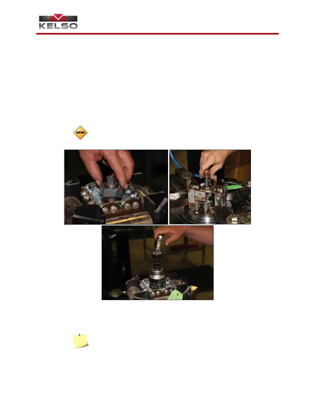
6.2 Valve Completion
1. Thread the adjustment screw jam nut clockwise onto the top of the
adjustment screw until it comes into contact with the spring block,
locking the adjustment screw in a static position (Figure 6.12, 6.13).
Once the jam nut is in this position, it should be torqued according to
the following specified values based on the valve model:
a. For valve models JS75/S, JS75H/HS, JS165H/HS, and
JS75XH/XHS, the jam nut should be torqued to 25 ft. – lbs.
b. For valve models JS75L/LS, JS165L/LS, JS75XL/XLS,
JS75LT/LTS, and JS165LT/LTS, the jam nut should be
torqued to 100 in. – lbs.
Ensure that they adjustment screw remains static while torquing the jam
nut as to prevent the adjustment screw from rotating and changing the
valve’s setting.
2. Install a wire and lead seal through the jam nut and the spring block
and crimp the lead onto the wire, preventing unintentional adjustment
of the valve (Figure 6.15). Install the debris screen (If applicable).
NOTE: The wire seal must be stamped with your company’s facility QA
Code as established by AAR.
 Loading...