Do you have a question about the Kemppi FitWeld 300 and is the answer not in the manual?
Specifies the input voltage range and frequency for the welding machine.
Indicates the maximum apparent power (kVA) the machine can draw.
Details the welding current and voltage ratings at different duty cycles.
Defines the operational range of welding current and voltage.
Specifies the requirements for the power connection cable and fuse.
States the voltage output when the welding arc is not initiated.
Information on power factor and efficiency at maximum current.
Covers maximum wire spool size, external dimensions, and weight.
Lists compatible filler wire types and their diameter ranges.
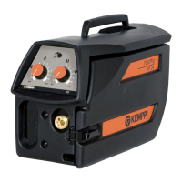
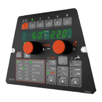
Identifies adjustments and indicators on the front panel.
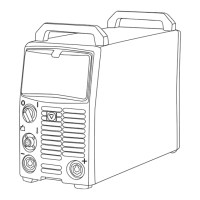
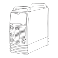
Details connectors and the main switch located on the back panel.
Describes switches, adjustments, and lighting within the spool compartment.
Visual guide to key internal parts like cooling fans and wire feeder motor.
Provides tips on screw replacement and essential safety checks.
Presents the overall schematic showing interconnections of major components.
Lists the functions and identifies components of the Z001 card.
Details the default configurations for jumpers on the Z001 card.
Step-by-step guide for measuring DC-link voltage using a multimeter.
Instructions for testing primary rectifier diodes with a digital multimeter.
Overview of the secondary rectifier's main components and their roles.
Details on measurement points for secondary diodes and damping resistors.
Describes card functions, important notes, and adjustments for wire feed speed.
Details the functions of the panel card, including voltage filtering and indicator LEDs.
Explains the function of the gas pressure switch and its adjustment.
Procedure for correctly mounting IGBT modules onto the heat sink, including torques.
Guidance on installing the secondary diode unit, including screw type and torque.
| Brand | Kemppi |
|---|---|
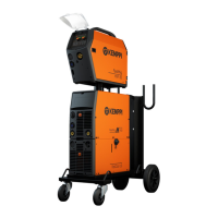
| Model | FitWeld 300 |
| Category | Welding System |
| Language | English |