ASS
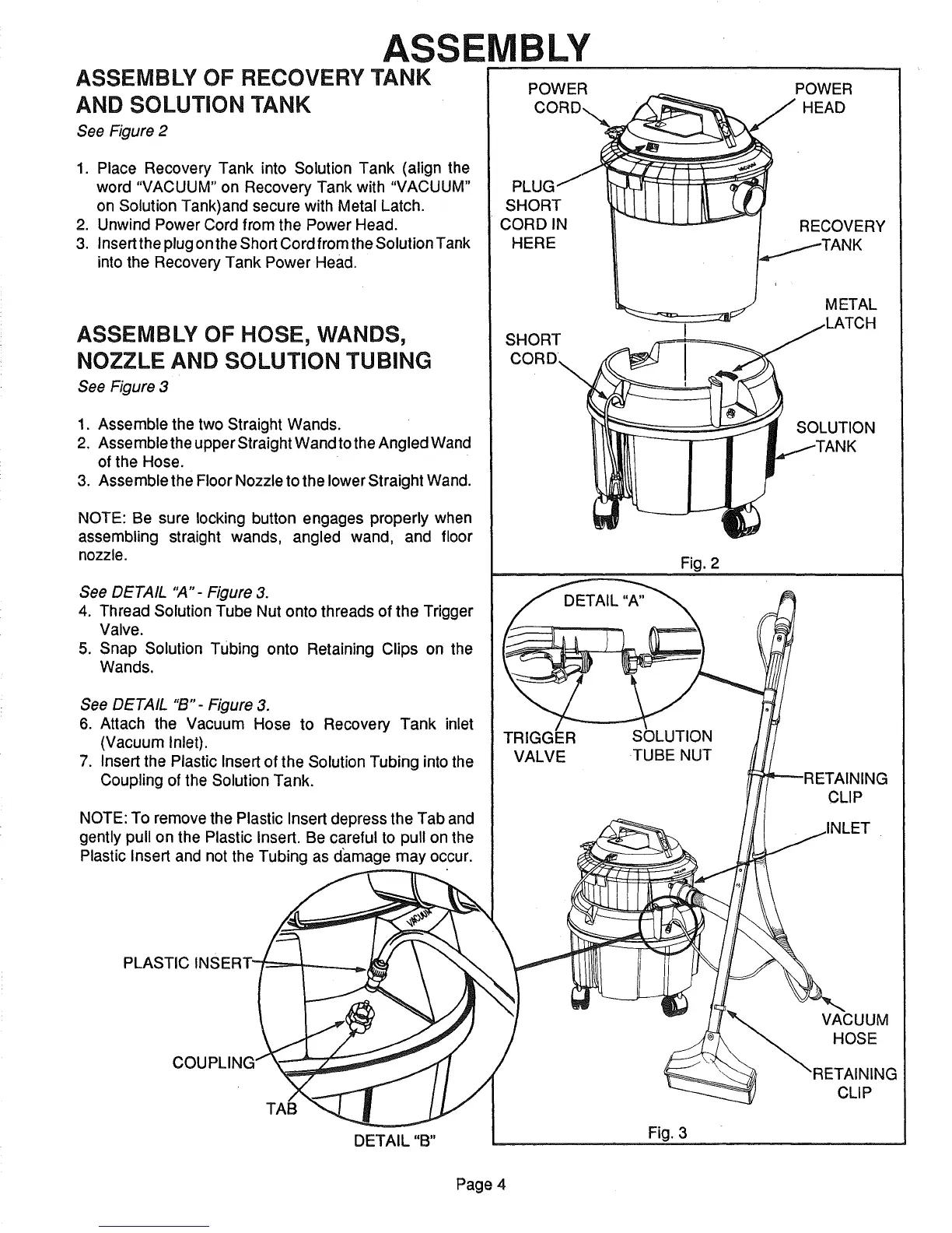
ASSEMBLY OF RECOVERY TANK
AND SOLUTION TANK
See Figure 2
1. Place Recovery Tank into Solution Tank (align the
word "VACUUM" on Recovery Tank with "VACUUM"
on Solution Tank)and secure with Metal Latch.
2. Unwind Power Cord from the Power Head.
3. Insert the plug on the Short Cord from the Solution Tank
into the Recovery Tank Power Head.
ASSEMBLY OF HOSE, WANDS,
NOZZLE AND SOLUTION TUBING
See Figure 3
1. Assemble the two Straight Wands.
2. Assemble the upper Straight Wand to the Angled Wand
of the Hose.
3. Assemble the Floor Nozzle to the lower Straight Wand.
NOTE: Be sure locking button engages properly when
assembling straight wands, angled wand, and floor
nozzle.
See DETAIL "A"- Figure 3.
4. Thread Solution Tube Nut onto threads of the Trigger
Valve.
5. Snap Solution Tubing onto Retaining Clips on the
Wands.
See DETAIL "B'- Figure 3.
6. Attach the Vacuum Hose to Recovery Tank inlet
(Vacuum Inlet).
7. Insert the Plastic Insert of the Solution Tubing into the
Coupling of the Solution Tank.
NOTE: To remove the Plastic Insert depress the Tab and
gently pull on the Plastic Insert. Be careful to pull on the
Plastic Insert and not the Tubing as da.mage may occur.
PLASTIC INSERT-
COUPLING
DETAIL "B"
LY
POWER POWER
HEAD
SHORT
CORDIN
HERE
RECOVERY
SHORT
METAL
SOLUTION
DETAIL "A"
TRIGGER
VALVE
Fig. 2
SOLUTION
TUBE NUT
CLIP
3
Fig. 3
VACUUM
_ HOSE
Page 4