Do you have a question about the Kenmore 795.78319.802 and is the answer not in the manual?
Details electrical ratings, voltage, current, and energy consumption of the refrigerator.
Specifies compressor capacity, pressure, and refrigerant type for optimal cooling.
Lists part numbers for common replacement components like compressor, fan motor, and sensors.
Instructions for removing refrigerator doors, gaskets, and aligning doors for proper sealing.
Step-by-step guide for removing the fan and fan motor assembly.
Details the defrost control assembly, sensor, and fuse for automatic defrosting.
Procedures for replacing refrigerator and freezer compartment lamps.
Comprehensive steps for removing and reinstalling the pull-out drawer and glide-out basket.
Instructions for removing and reinstalling the cover valve component.
Explains compressor, PTC, OLP roles, their composition, and usage notes.
Defines the Overload Protector (OLP) and its role in protecting the compressor motor.
Step-by-step instructions for removing the PTC cover and the compressor combo unit.
Provides a detailed schematic of the refrigerator's electrical connections for troubleshooting.
A flowchart to diagnose issues related to the compressor and electrical components.
Diagnoses issues with starting devices, OLP, coils, wiring, and fan motors.
Correlates complaints with points to check and remedies for common issues.
Explains refrigeration cycle issues like leakage, clog, and low compression for diagnosis.
Outlines the operational steps of the icemaker, from power on to harvest mode.
Describes ice making, harvest, and fill/park modes, including water supply adjustments.
Lists error codes displayed on the ice maker control panel and their causes.
Explains various functions like temperature display, fan motor control, ULTRA ICE, and lamp auto-off.
Details the PCB power circuit, assembly, and parts list for internal components.
Provides sensor resistance values at different temperatures for accurate diagnosis.
A table to troubleshoot common refrigerator problems like display issues, no cooling, and incorrect temperatures.
A detailed schematic of the PWB main assembly, illustrating component interconnections.
Exploded view diagram showing external case components and their assembly.
Exploded view diagram of freezer compartment parts for identification.
Exploded view diagram of refrigerator compartment parts, including shelves and drawers.
Exploded view of door components, including bins, handles, and gaskets.
Exploded view of water and ice maker system components for service.
| Brand | Kenmore |
|---|---|
| Model Number | 795.78319.802 |
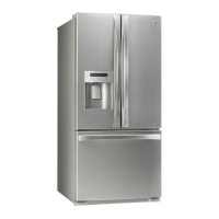
| Type | French Door |
| Ice Maker | Yes |
| Water Dispenser | Yes |
| Finish | Stainless Steel |
| Energy Star Certified | Yes |