EasyManua.ls Logo

Kenwood A-71 User Manual

Kenwood A-71
34 pages
To Next Page IconTo Next Page
Page #1 background imageLoading...
Page #1 background image
STEREO
INTEGRATED
AMPLIFIER
a7
KENWOOD
SERVICE
MANUAL
C
1987-9
PRINTED
IN
JAPAN
B51-3342-00(T)1,
272
Remote
controller
ass’y
(A70-0184-05}
Dressing
piate
(Remote
control)
Knob
(Balance)
(BO3-2323-04)
(K29-2201-04)
Knob
(Bass,
Treble)
Metallic
cabinet
Knob
(Volume)
(K29-2506-14)
x
2
{A01-1584-01)
(K29-2767-04)
Panel
ass’y
(A20-5361-02)
KENWOOD
sa
reat
Mic
jack
Nee
oer
Oe
(£1
1-0159-05)
Phone
jack
(Phones)
Dressing
plate
(LED)
Knob
(Mic
mixing)
(E11-0160-05)
(BO3-2334-04)
(K29-2737-04)
Binding
post
(GND)
Screw
terminal
board
(4P)
Phono
jack
(2P)
|
AC
outlet*
Power
cord
bushing
(NO8-01
28-35)
(E20-0455-05)
(E13-0297-05)
(EO3-)
(J42-0083-05)
Phono
jack
(3P)
(E13-0309-05)
Slide
switch
Slid2
switch*
(S31-2113-05)
(S31
-2083-05)
x
2
Phono
jack
(4P)
Rertangular
(E13-0497-05)
receptacle
(Et3-0411-05)
EY
.
!
AC
10
*
Phono
jack
(6x
Phono
jack
(6P)
ps
eae
(E13-0621
omy
1
(E13-0621-05)
|
Foot
.?
Phono
jack
(8P)
Miniature
phone
jack*
(J02-0366-05)
x
4
©.
(E13-0814-05)
(E11-)
Fin
(J12-0094-05)
x
2
«
&>
*
Refer
to
parts
list
on
peage
34.
Question and Answer IconNeed help?

Do you have a question about the Kenwood A-71 and is the answer not in the manual?

Kenwood A-71 Specifications

General IconGeneral
TypeIntegrated Amplifier
Frequency Response5Hz - 100 kHz
Signal-to-Noise Ratio110 dB
Damping factor100
OutputSpeaker
Speaker load impedance4Ω - 16Ω

Summary

FUNCTION

Front Panel Controls Overview

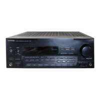
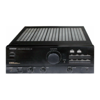
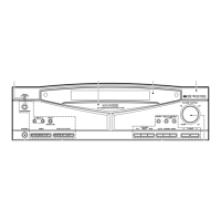
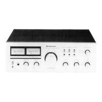
Overview of front panel controls including power, headphones, input selection, volume, balance, muting, and tone.

Special Function Switches

Details on DAT DIRECT and CD DIRECT switches for enhanced audio quality.

Microphone Input and Mixing

Explanation of the MIC jack and the MIC MIXING control for microphone input.

CIRCUIT DESCRIPTION

Audio Unit Component Functions

Details the function and operation of integrated circuits within the audio unit.

Control Unit Component Functions

Explains the function of components within the control unit (X11-2452-71).

Amplifier Unit Component Functions

Details components of pre-amplifier, sub, and main amplifier units.

Microprocessor IC Details

Terminal connection diagram and keymatrix connection for the microprocessor IC1.

Detector and Reception ICs

Details supply voltage detector (IC4) and remote control reception module (A1).

Selector IC Details

Details the CX7977 selector IC, its block diagram, and analog circuitry.

Motor Driver IC

Details the BA6109 motor driver IC, its block diagram, and power derating curve.

ADJUSTMENT/REGLAGES/ABGLEICH

Idle Current Adjustment

Procedure for adjusting the idle current using a DC voltmeter and specific terminals.

Related product manuals