EasyManua.ls Logo

Kenwood A-58 Service Manual

Kenwood A-58
44 pages
To Next Page IconTo Next Page
Page #1 background imageLoading...
Page #1 background image
Mca
68
KENWOOD
SERVICE
MANUAL
©
1994-8
PRINTED
IN
KOREA
B51-4909-00(
K)
2651
Knob
(Input)
Metallic
cabinet
Knob
Indicator
Panel*
Knob
(Volume)
Foot
(Amp)
(K29-6024-04)
(A01-3162-02)
(K29-5968-02)
(B12-0245-03)
(A60-)
(K29-6024-04)
(J02-1111-04)
KENWOOD:
Knob
(Power)
,
Knob
Phone
jack
(Mic)
Knob
(Dolby/D
sound)
(K29-5969-13)
(K29-5968-02)
(E11-0206-05)
(K29-5969-13)
Phone
jack
(Phones)
_—_
Foot
(Front)
Front
glass
Knob
(Mic/Dual
sound)
(E11-0208-05)
(JO2-1040-05)
|
(B10-2050-03)
(K29-3886-04)
Photo
is
A-58.
*Refer
to
parts
list
on
page
45.
Question and Answer IconNeed help?

Do you have a question about the Kenwood A-58 and is the answer not in the manual?

Kenwood A-58 Specifications

General IconGeneral
BrandKenwood
ModelA-58
CategoryAmplifier
LanguageEnglish

Summary

EXTERNAL VIEWS

A-58 Rear Panel Connections

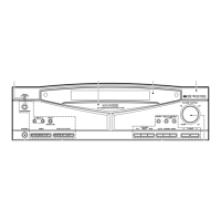
Diagrams and labels for the rear panel connections of the A-58 unit.

EXTERNAL VIEWS

A-68 Rear Panel Connections

Diagram and labels for the rear panel connections of the A-68 unit.

ACCESSORIES

Included Accessories List

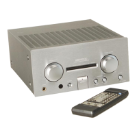
List of accessories supplied with the amplifier unit, including diagrams.

AMPLIFIER UNIT CONTROLS

Front Panel Controls

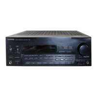
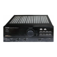
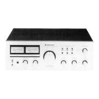
Identifies and describes controls on the front panel of the amplifier unit.

EQUALIZER UNIT CONTROLS

Front Panel Controls

Identifies and describes controls on the front panel of the equalizer unit.

REMOTE CONTROL OPERATION

Key Functions and Operation

Explains the operation of various keys on the remote control unit.

DISASSEMBLY FOR REPAIR

Unit Disassembly Procedures

Instructions for disassembling front panel, rear panel, and internal PCBs.

CIRCUIT DESCRIPTION

System Block Diagram

Overview of the main functional blocks and signal flow within the amplifier.

CIRCUIT DESCRIPTION

Initial Setting Procedures

Details on how to perform initial setup and reset the unit's functions.

CIRCUIT DESCRIPTION

Test Mode Operations

Procedures for entering test mode and confirming key functionality.

CIRCUIT DESCRIPTION

Microcomputer (μ-COM) Details

Block diagram and pin information for the main microcomputer IC.

WIRING DIAGRAMS

System Wiring Connections

Diagrams showing electrical connections between various units and components.

PC BOARD VIEWS

Component Layouts

Component layout views of the main unit's printed circuit boards.

EXPLODED VIEWS

Component Assembly Diagrams

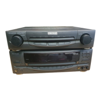
Visual breakdown of unit components for assembly and identification.

PARTS LIST

Component Parts Listing

List of parts with reference numbers, descriptions, and destination codes.

SPECIFICATIONS

Technical Performance Data

Detailed technical specifications for the A-58 and A-68 models.

Related product manuals