EasyManua.ls Logo

Kenwood DDX512 User Manual

Kenwood DDX512
86 pages
To Next Page IconTo Next Page
Page #1 background imageLoading...
Page #1 background image
This product uses Lead Free solder.
This product complies with the
RoHS directive for the European market.
© 2008-2 PRINTED IN JA PAN
B53-0620-10
(
N
)
519
MONITOR WITH DVD RECEIVER
DDX5022/5022Y/5032
/5032M/512/52RY
DNX5120/512EX/5220/5220BT
SERVICE MANUAL
* Depends on the models. Refer to the parts list.
Remote controller *
(A70-2083-15)
Size AAA battery
Not supplied
RC-DV340
Escutcheon
(B07-3165-02)
Mounting hardware assy
(J22-0657-03)
Lever
(D10-4589-04) x2
Escutcheon *
(B07-3172-12)
DC cord *
(E30-6796-05)
DC cord *
(E30-6795-05)
Cord with plug *
(E30-6785-05)
Screw set *
(N99-1779-15)
Adhesive double-
coated tape
*
(H30-0595-04)
Antenna module(GPS-ANT)
(W02-5305-05)
Mounting hardware *
(J21-9867-04)
Panel assy
(A64-4530-11): DDX512
(A64-4532-11): DDX5022/5022Y
(A64-4535-11): DNX5120
(A64-4536-11): DNX5220BT
(A64-4537-11): DNX5220
(A64-4539-01): DDX5032/5032M
(A64-4540-01): DDX52RY
(A64-4551-01): DNX512EX
Illustrations is DNX5220BT
Except K,R type Only DNX Only DNX5220BT
The IC3, and IC11 in the DVD unit (X37-1100-03) are not replaceable components.
When these ICs are defective, replace the whole DVD mechanism assembly (X92-6160-00).
You cannot replace only the board.
Microphone *
(W01-1718-05)
Question and Answer IconNeed help?

Do you have a question about the Kenwood DDX512 and is the answer not in the manual?

Kenwood DDX512 Specifications

General IconGeneral
BrandKenwood
ModelDDX512
CategoryCar Receiver
LanguageEnglish

Summary

DVD Mechanism and Block Diagram

DVD Unit Block Diagram

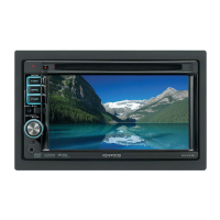
Functional overview of the DVD unit and its interconnections.

System Block Diagram

Main Unit Architecture

Overall system block diagram illustrating interconnections between components.

System Block Diagram - Connectivity

System Interfaces and Signals

Block diagram showing connectivity and signal flow of the system.

System Block Diagram - Display/Control

Display Panel and Control Connections

Block diagram illustrating display and control signal paths.

Component Descriptions - Video Control Unit

Component Descriptions - Video Control Unit (Cont.)

Component Descriptions - Video Unit

Component Descriptions - DVD Unit

Microcomputer Terminal Description

IC104 Pin Functions (1-38)

Details pin assignments and functions for IC104 (System Microcomputer).

Microcomputer Terminal Description (Cont.)

IC104 Pin Functions (39-79)

Continues pin function details for IC104.

Microcomputer Settings and Matrix

Test Mode Overview

Entering and Navigating Test Mode

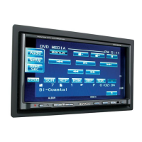
Methods to enter test mode and screen transition.

Test Mode Screen Details

Test Mode - Serial Entry and Adjustments

Serial Number Entry and DVD Service

Procedures for serial number entry and DVD service information.

Test Mode - Screen and iPod Tests

Direct Select, Touch, HPOSI, and iPod Tests

Details various test modes for screen and iPod communication.

Test Mode - Auto Adjust, Inverter, NAVI

Auto Adjust, Inverter, and NAVI Tests

Explains auto adjust, inverter frequency, and NAVI checks.

Test Mode - Key and DVD Functions

Remote Controller and DVD Checks

Key functions and DVD video/audio testing procedures.

Test Mode - Audio, AVIF, Screen, DC Offset

Audio, AVIF, Screen, and DC Offset Settings

Covers default settings and DC offset handling.

Test Mode - E2PROM and Security

E2PROM Clearing and Security Code Entry

Procedures for clearing E2PROM and writing security codes.

Adjustment Procedures

Pickup Replacement Adjustments and Checks

Steps for pickup replacement adjustment and playback checks.

Adjustment Procedures - Flicker, VCOM, Display

Flicker, VCOM, and Horizontal Display Adjustments

Procedures for flicker, VCOM, and display position adjustments.

Adjustment Screens - Graphic and NAVI

Graphic and NAVI Adjustment Screens

Details adjustment screens for Graphic and NAVI displays.

Adjustment Procedures - Graphic Details

Graphic Adjustment Steps

Step-by-step guide for Graphic display adjustments.

Adjustment Procedures - NAVI Details

NAVI Screen Symmetry and Range Adjustments

Adjustments for NAVI screen symmetry and range.

Adjustment Procedures - Touch Panel

DDX NAVI Symmetry and Touch Panel Calibration

Adjustments for DDX NAVI symmetry and touch panel calibration.

Parts List - Accessories and Mechanical

Parts List - Electronic Components (Video Control)

Parts List - Electronic Components (Video Control Cont.)

Parts List - Electric Unit

Parts List - Electric Unit (Cont.)

Parts List - Video Unit

Parts List - Video Unit (Cont.)

Parts List - DVD Unit

Parts List - DVD Unit (Cont.)

Parts List - Daughter Unit and Mechanism

Specifications - DNX Models

Specifications - DDX Models

Specifications - DNX/DDX Models (Cont.)

Related product manuals