EasyManua.ls Logo

Kenwood DP-7010 Service Manual

Kenwood DP-7010
42 pages
To Next Page IconTo Next Page
Page #1 background imageLoading...
Page #1 background image
COMPACT
DISC
PLAYER
DP-7010
SERVICE
MANUAL
KENWOOD
(©1989-2
PRINTED
IN
JAPAN
B51-3677-00(0)2842
Panel
(Tray)
Metallic
cabinet
(A29-0139-03)
(A01-1514-02)
Knob
(POWER)
Panel
ass'y*
Knob
(1~20)
(K29-3363-14)
(A20-)
(K29-3493-04)
x
20
Insulator
ass'y
(Front,
Rear
L)
Front
glass
Phone
jack
(PHONES)
Remoto
controller
ass'y
(J02-0397-15)
x
3
(B10-0979-13)
(E11-0190-05)
(A70-0251-05)
Phono
jack
(LINE
OUTPUT)
Transmitting
ass'y
(OPTICAL)
DIGITAL
OUTPUT
Power
cord
bushing
AC
power
cord*
(E13-0483-05)
(W02-0936-05)
(J42-0083-05)
(E30-)
ting
9)
poe
i
CJ
AC
110-120V~
«em
AC
220-240V~
[
Optica
@|
a
Cap
(B09-0068-05)
Insulator
ass'y
(Rear
R)
Phono
jack
(COAXIAL)
DIGITAL
OUTPUT
Slide
switch
(Power
type)*
(J02-0396-15)
(E13-0137-05)
(S31-2128-05)
In
cormplicance
with Federal
Regulations,
following
are
reproduc-
*
Refer
to
parts
list
on
page
71.
tions
of
labels
on,
or
inside
the
product
relating
to
laser
product
safety.
KENW/OOD-Corp.
certifies
this
equipment
conforms
to
DHHS
Regulations
No.
21
CFR
1040.
10,
Chapter
1,
Subchapter
J.
DANGER
:
Laser
radiation
when
open
and
interlock
defeated.
AVOID
DIRECT
EXPOSURE
TO
BEAM.

Other manuals for Kenwood DP-7010

Question and Answer IconNeed help?

Do you have a question about the Kenwood DP-7010 and is the answer not in the manual?

Kenwood DP-7010 Specifications

General IconGeneral
BrandKenwood
ModelDP-7010
CategoryCD Player
LanguageEnglish

Summary

SYSTEM CONNECTIONS

Amplifier and Audio Connections

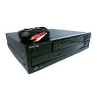
Details analog and digital audio connections to amplifiers.

DISASSEMBLY FOR REPAIR

Pickup Removal

Steps to detach the optical pickup assembly from the player.

CIRCUIT DESCRIPTION - Component Overview

CIRCUIT DESCRIPTION - CD Player Unit

CIRCUIT DESCRIPTION - Mode Operations

Set Mode and Test Mode Functions

Covers set mode flowcharts and test mode operations.

CIRCUIT DESCRIPTION - Test Mode Flowcharts

Test Mode Operational Guides

Visual guides for specific test mode procedures and operational flowcharts.

CIRCUIT DESCRIPTION - Microprocessor and RF Amplifier

CIRCUIT DESCRIPTION - Servo and Signal Processing

Servo Control and DSP ICs

Details servo control ICs, digital signal processor, and system control circuits.

CIRCUIT DESCRIPTION - Digital Conversion and Filtering

CIRCUIT DESCRIPTION - D.P.A.C IC

MECHANISM OPERATION DESCRIPTION

ADJUSTMENT PROCEDURES

Laser Power and VCO Adjustment

Steps for adjusting laser power and VCO frequency.

Servo Balance Adjustments

Procedures for adjusting tracking error, focus error, and gain balances.

SCHEMATIC DIAGRAM

Full Circuit Diagram

Detailed electrical schematic of the entire CD player circuit.

PARTS LIST

Related product manuals