EasyManua.ls Logo

Kenwood KDC-216S User Manual

Kenwood KDC-216S
18 pages
To Next Page IconTo Next Page
Page #1 background imageLoading...
Page #1 background image
© 2000-12 PRINTED IN JAPAN
B51-7701-00(S) 1752
SERVICE MANUAL
CD RECEIVER
KDC-216S/2018
CRSC
ADJ
KDC-216S
AUD
PWR OFFLOUD SCAN RDM REP
AME
AUTO
COMPACT
DIGITAL AUDIO
45Wx4
Knob(RELEASE)
(K24-3665-04)
Knob(EJ)
(K24-3653-04)
Front glass
(B10-3294-01:216S)
(B10-3297-01:2018)
Panel assy
(A64-2202-02:216S)
(A64-2209-02:2018)
Knob (Q)
(K24-3652-04)
Knob(VOL)
(K25-1256-03)
Knob(1-6)
(K25-1253-03)
Knob(CLK)
(K25-1254-03)
Knob(FM/AM)
(K25-1255-03)
DC cord
(E30-4783-05:216S)
(E30-4784-05:2018)
Plastic cabinet assy
(A02-1486-13)
Mounting hardware assy
(J21-9641-03)
Stay
(J54-0606-04)
Screw set
(N99-1610-15)
Lever
(D10-4589-04)
Screw set
(N99-1632-05)
KDC-216S
Question and Answer IconNeed help?

Do you have a question about the Kenwood KDC-216S and is the answer not in the manual?

Kenwood KDC-216S Specifications

General IconGeneral
BrandKenwood
ModelKDC-216S
CategoryReceiver
LanguageEnglish

Summary

KDC-216S Component Identification

Front Panel Controls

Identifies and labels the various knobs and buttons on the front panel of the KDC-216S unit.

Physical Assembly Parts

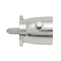
Details external parts including cabinet, mounting hardware, DC cord, and lever.

System Block Diagram

Component Descriptions

Switch Unit Components

Details components within the switch unit, including their part numbers, functions, and operating conditions.

Electric Unit Components

Lists components in the electric unit, their part numbers, functions, and operational details.

Microcomputer Terminal Description

Adjustment and Test Modes

Entering and Exiting Test Mode

Instructions for activating and deactivating the unit's test mode for diagnostics.

Adjustment Mode Procedures

Steps for performing various adjustments and their default values.

Printed Circuit Board Layouts

Schematic Diagrams

CD Player Unit PC Board Layouts

CD Mechanism Schematic

Switch Unit and LCD Schematic

CD Mechanism Circuit Diagram

Exploded Views

CD Mechanism Assembly

Illustrates the physical arrangement of parts for the CD mechanism assembly.

Unit Assembly Details

Shows the exploded view of the main unit's components for assembly reference.

Parts List

Switch Unit Components

Comprehensive list of parts for the switch unit, including numbers and descriptions.

Electric Unit Components

Comprehensive list of parts for the electric unit, including numbers and descriptions.

Parts List - Electric and CD Player Units

Electric Unit Component Details

Continuation of the parts list for the electric unit.

CD Player Unit Component Details

List of parts specific to the CD player unit.

Parts List - Continued

Electric Unit Component Details

Further listing of parts for the electric unit.

CD Player Unit Component Details

Further listing of parts for the CD player unit.

Parts List - CD Player and Mechanism

CD Player Unit Components

Listing of parts for the CD player unit.

Mechanism Assembly Components

Parts list for the CD mechanism assembly.

Parts List - Mechanism Assembly (Continued)

Specifications Overview

FM and AM Section Specifications

Details on frequency range, sensitivity, and selectivity for FM and AM reception.

CD Section Performance

Specifications related to the CD player, including laser, filter, and audio output.

Amplifier and General Features

Information on amplifier output, tone controls, operating voltage, and physical dimensions.

Related product manuals