Do you have a question about the Kenwood KDC-225/MR and is the answer not in the manual?
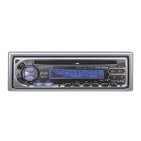
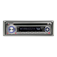
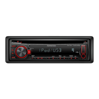
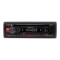
Identification of panel assemblies for KDC-225, KDC-225MR, and KDC-2025 models.
Identification of front glass assemblies for KDC-225, KDC-225MR, and KDC-2025.
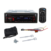
Lists various accessory parts like DC cord, escutcheon, screws, and remote controller.
Diagram showing signal input paths for Tuner and CD/VCD sources.
Central processing unit and its control signals within the system.
Block diagram of audio amplification and power output stages.
Includes EEPROM, Remote Control IC, and other interface circuits.
Shows LCD driver and panel signal connections.
Descriptions of ICs and transistors within the Switch Unit.
Descriptions of ICs, transistors, and regulators in the Electric Unit.
Descriptions of ICs and transistors used in the CD Player Unit.
Descriptions of diodes and driver components in the CD Player Unit.
Detailed description of each pin's function for the system microprocessor.
Instructions for entering and exiting the unit's test mode.
Describes the unit's status and display upon entering test mode.
Procedures for testing tuner, RDS reception, and CD functionality.
Steps for adjusting audio parameters and accessing menu functions.
Information on viewing version, segments, and counts in test mode.
Foil side view of the Electric Unit PCB showing component placement and routing.
Continuation of the Electric Unit PCB foil side view.
Table mapping component reference numbers to PCB addresses.
Component side view of the CD Player Unit PCB.
Foil side view of the CD Player Unit PCB showing routing.
Component side view of the Switch Unit PCB.
Foil side view of the Switch Unit PCB showing routing.
Circuit diagram for the main electric unit.
Schematics for signal selector and RDS demodulator.
Circuitry connecting to the system microprocessor.
Schematics detailing servo control and audio processing circuits.
Circuit diagrams showing the interface with the CD mechanism.
Schematics for power distribution and control signal logic.
Schematic diagram illustrating the Switch Unit's internal circuitry.
Diagram showing the DC cord wiring and connector pin assignments.
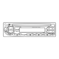
Visual representation of the Switch Unit's front panel controls and displays.
Details pin functions and connections for the Switch Unit.
Detailed circuit diagrams for the Switch Unit's operation.
Table correlating component part numbers for various models.
Schematics for the CD Player's signal processing functions.
Circuit diagrams for CD motor control and disc loading mechanisms.
Diagrams showing the interface connections to the main unit.
Schematics for servo control and laser tracking systems.
Specific component details for the DPU1 optical pickup.
Details on screws, washers, and their part numbers for the CD mechanism.
Identification of major sub-assemblies and parts within the CD mechanism.
Exploded view of the main unit's chassis, housing, and related parts.
Exploded view of the unit's front panel, display, and interface components.
Details on screws and mounting hardware for the main unit.
List of parts for the main unit and the switch unit.
Detailed list of components for the electric unit.
Detailed list of components for the CD player unit.
Detailed list of components for the mechanism assembly.
Guide to identifying capacitor types, shapes, temp coefficients, and values.
Guide to identifying resistor types, shapes, temp coefficients, and values.
Detailed performance specifications for FM and AM tuner sections.
Technical specifications for CD playback and processing.
Specifications for the amplifier section and general unit characteristics.
| Bluetooth | No |
|---|---|
| Display Type | LCD |
| RDS | Yes |
| CD Player | Yes |
| MP3 Playback | Yes |
| WMA Playback | Yes |
| Detachable Faceplate | Yes |
| Remote Control | Yes |
| Channels | 4 |
| Max Power Output | 50W x 4 Channels |
| RMS Power Output | 22W x 4 Channels |
| Tuner | AM/FM |
| Aux Input | Yes |